Televisor Kit Build · Volume 2
How the Kit Works
Strip away the case and the kit is four mechanisms working against each other in a stable equilibrium: a disc that decomposes a picture into a sequence of moments, a lamp that supplies brightness one moment at a time, a sensor that reports where the disc has got to, and a control loop that uses that report to hold the disc exactly in step with whatever is arriving at the input socket. Remove any one and the others produce nothing — not a degraded picture, but no picture at all. This volume describes each of the four and, more importantly, describes how they depend on one another, because almost every fault a builder meets in Vol 8 is a failure of one of those dependencies rather than a failure of a part.
2.1 Two Rings of Holes, Doing Two Different Jobs
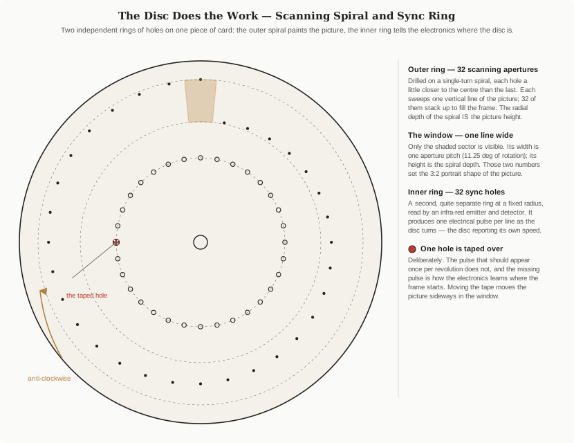
Everything starts with the disc, and the disc is cleverer than it looks. It carries two entirely separate sets of holes, drilled at different radii, read by different things, doing unrelated jobs.
The outer ring is the picture. Thirty-two apertures are set out on a single-turn spiral: each one sits a little closer to the centre than the last, so that over one revolution the set of them sweeps the whole picture area. Only a small window of the disc is ever visible — everything else is masked — and in that window, at any instant, exactly one aperture is passing. That aperture traces one vertical line of the picture as it crosses the window. The next aperture, being slightly nearer the centre, traces the adjacent line. Thirty-two apertures, one revolution, thirty-two lines, one complete frame.
Two consequences follow from that geometry, and both are worth holding onto because they explain things that otherwise look arbitrary. First, the radial depth of the spiral is the picture height — the difference in radius between the first aperture and the last is literally how tall the image is. Second, the picture width is an angle, not a length: the window is one aperture pitch wide, which is 360 degrees divided by 32, or 11.25 degrees of rotation. Between them those two numbers fix the shape of the picture, and the club standard’s portrait 3:2 ratio is the result of choosing them to suit.
A third consequence is less welcome. Because each line is traced along an arc rather than a straight line, the picture is not a rectangle but a shallow sector of a circle — every vertical line is very slightly curved, and the curvature is worse on a small disc than a large one. The association’s standards page addresses this directly, recommending consistent “right-handed optics” (view from the right-hand side of the disc, rotate anti-clockwise) precisely so that a picture recorded against one handedness and viewed against the other does not compound the distortion into something genuinely unpleasant.
The inner ring is the clock. A second, quite separate ring of 32 holes sits at a fixed radius, unrelated to the spiral, and is read not by the eye but by an infra-red emitter and detector facing each other across the disc. As the disc turns, that pair produces one electrical pulse per hole — one pulse per line, 400 of them per second at the standard frame rate. This ring is the disc telling the electronics how fast it is going and where it has got to. It carries no picture information whatsoever.
2.2 The Hole That Isn’t There
One hole in the sync ring is covered over. Deliberately, with a scrap of insulating tape, by the builder, during commissioning.
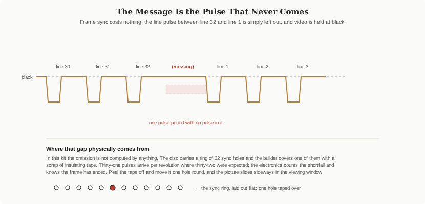
This is the most elegant idea in the whole machine, and it deserves to be understood rather than merely performed. The electronics needs two different pieces of timing information: when each line begins, and when each frame begins. The sync ring gives it the first for free — one pulse per line. The second it gets by subtraction. With one hole masked, the disc delivers thirty-one pulses per revolution where thirty-two were expected. The controller counts pulses, notices the one that failed to arrive, and concludes that a revolution has ended and the next frame starts here.
The absence of an expected pulse is the message. Nothing is added, no second channel exists, no distinct pulse shape has to be recognised — and the mechanism is not computed at all, it is built into the disc. The NBTVA’s own construction guide for its larger club televisor describes exactly this step and exactly this consequence: cover any one of the 32 synchronising ring holes with black insulating tape, and the position of the covered hole determines where the picture sits horizontally in the viewing frame. If the picture is off to one side, the fix is not an electronic adjustment; it is to peel the tape off and move it one hole round.
This is worth dwelling on because it inverts a builder’s instinct. A picture sitting wrong in the frame looks like a calibration problem and is in fact a geometry problem, solved with a fingernail rather than a screwdriver.
The same guide gives the diagnostic signature to look for on an oscilloscope: a regular stream of pulses with a missing pulse every thirty-one. That single observation, taken early, validates the disc, the sensor, its alignment, and the tape position all at once, and Vol 8 puts it fifth in the commissioning order for exactly that reason.
2.3 Dragging the Motor Into Step
The motor in this kit is a small brushed DC motor, and by itself it is hopeless at the job. Applied to a supply it simply runs, at whatever speed the load and the voltage happen to produce, drifting with battery state and friction and temperature. It has no governor, no tachometer feedback of its own, no gearbox, and nothing that knows what 12.5 revolutions per second is.
What locks it to the right speed is a phase-locked loop, and the signal it locks to is the video itself.
The chain runs like this. The incoming NBTV waveform reaches a sync separator, which discards the picture and keeps only the sync pulses — possible because those pulses live at a voltage the picture is never permitted to reach, the “blacker than black” region that Vol 3 covers in detail. That stream of pulses represents the rate at which the source expects lines to be displayed. Meanwhile the optical sensor on the disc delivers its own stream of pulses, representing the rate at which the disc is actually displaying them. A phase comparator — classically a CD4046, and in the association’s newer club controller a PIC microcontroller emulating one — compares the two streams and produces an error. A loop filter smooths that error into a control voltage, and a motor driver turns it into current. If the disc is running slow, the motor is pushed harder; if fast, eased off.
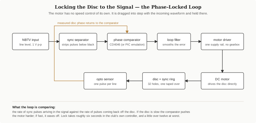
The behaviour this produces is characteristic enough to be a diagnostic in itself, and the association’s documentation of its own controller describes it with unusual candour. On switch-on the disc twitches; it spins up as synchronising pulses arrive; it makes a familiar grinding noise as it approaches lock; and finally the picture rolls and then stops rolling as correct framing comes into view. Mean time to frame lock is around six seconds, with a worst case a little over twelve. The controller can roll the picture in either direction to shorten the search. It is apt to overshoot by one line when rolling downward and then correct itself, and there is a degree of dithering even at perfect lock.
Two things follow for anyone using the kit. First, lock is audible before it is visible — the motor note settling is the earliest reliable sign that the loop has caught. Second, the loop needs a continuous signal to stay caught. A stream that stutters, a file that ends, a source that pauses to buffer, and the disc falls out of lock and has to re-acquire, with several seconds of rolling picture while it does. Vol 5 treats that as the central constraint on driving the kit from a live source, because it is.
There is a nice subtlety in the club controller’s design notes worth recording: certain manufacturers’ 4046 devices were found unsuitable for this application, because the circuit uses the phase comparator in an unusual way. A part that is nominally the same part, from a different foundry, does not necessarily work. That is the kind of detail that costs an evening if it is not known in advance.
2.4 The Light Path, and Why the Picture Is Dim
At any instant the entire picture is one illuminated hole. That sentence is the whole optical design, and everything else is an attempt to make it bearable.
Behind the disc sits a light source — in this kit an LED, in Baird’s Televisor a flat neon plate. The LED is modulated by the video signal: its brightness rises and falls with the voltage arriving from the source, continuously, as the disc turns. The aperture currently crossing the window admits light from that lamp to the viewer’s eye. As the aperture moves, the point of light moves with it; as the lamp’s brightness changes, that moving point changes brightness. Persistence of vision does the rest, and out of a single moving dot the eye assembles a picture.
The NBTVA’s construction chapter on LED light sources is detailed about what makes this work well. Brightness is the product of luminous intensity and beam angle, so both matter; LEDs that modulate without shifting hue give a visibly better picture than those that do not; orange high-brightness devices combine good efficiency with good visibility and happen to approximate the colour of the neon lamps they replaced, which is an aesthetic bonus rather than an engineering one. The club’s larger designs use a cluster — six devices is a workable number for modern ultra-bright parts — and the association’s own laser-cut club televisor uses twelve.
Between the lamp and the disc sit two unglamorous components that do most of the work of making the picture look like a picture:
- A diffuser spreads the lamp’s output so that illumination is even across the whole display area. The club’s own construction notes call making a good flat diffuser one of the hardest parts of a mechanical television project, and warn that LEDs sitting too close to the diffuser produce a visible halo.
- A mask trims the illuminated area down to the display frame, so that stray light does not leak past the picture and wash out the contrast.
The enclosure around the lamp is painted matt black on the outside faces that could reflect toward the viewer, and — because so little light gets through a small hole — matt white or foil-lined on the inside, to return as much of the lamp’s output as possible toward the aperture.
In front of the disc sits a magnifying lens, and in front of that a viewing hood: a black tunnel whose only job is to keep room light off the glass so that reflections do not compete with a picture that is, in absolute terms, extremely faint.
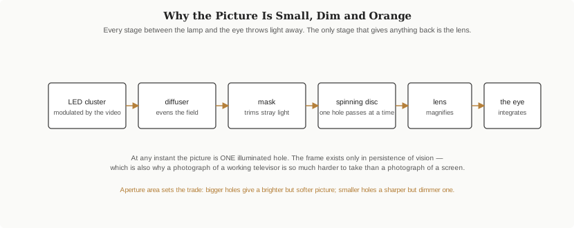
This chain explains the dimness completely, and it also explains a practical frustration worth warning about early: a working mechanical televisor is remarkably hard to photograph. A camera’s shutter does not integrate the way an eye does, and a short exposure will catch a few scattered dots rather than a picture. Anyone documenting a build should expect to experiment with exposure time — long enough to cover at least one full frame period of 80 milliseconds — rather than assuming the first disappointing frame means the set is not working.
2.5 Power, Input, and the One Adjustment That Matters
The kit runs from four AA cells, giving a nominal 6 volts for the motor, the control board and the lamp. That figure is worth stating carefully, because published figures for other NBTV televisors differ substantially and the numbers are easy to cross-contaminate: the NBTVA’s beginner construction chapter specifies a 12-volt supply for its general disc-televisor project, and the association’s laser-cut club televisor runs from an external 16-volt, 2-amp plug-top supply. Those are larger machines with heavier discs, brighter lamps and internal audio amplifiers. They are not this kit, and their supply figures should not be applied to it.
The input is a line-level audio signal, and the standard is specific about what that means: 1 volt peak to peak, from a source of 500 ohms or less into an input of 5 kilohms or more, on screened phono or coaxial cable with RCA connectors. The association’s own recommendation is a hi-fi CD player’s line output.
There is a documented trap in the alternative. Headphone or earphone outputs will work, but they roll off at the bottom of the band — usable from about 20 Hz where the standard asks for 2 Hz — and the standard’s low-frequency content is not decorative. It carries the slow brightness variations across a frame. A picture fed from an earphone socket is a picture with its large-scale shading impaired. The association thought this important enough to devote a handbook chapter to an amplifier specifically for CD-player earphone outputs.
The one adjustment a user is likely to need on the board itself is the signal amplitude preset, identified in forum discussion of this kit as R7. Its job is to scale whatever arrives at the input to the level the sync separator and lamp driver expect. Set too low, sync separation becomes unreliable and the disc will not hold lock; set too high, the picture clips.
And then there is polarity, which is not an adjustment on the board at all and catches nearly everybody. Not every playback device agrees on which way up the signal should come out. The kit’s own CD is reported to carry material in both polarities, which is itself a tacit admission of the problem. Get it wrong and the electronics interprets picture as sync and sync as picture — the results are not subtle. Vol 3 explains why the polarity convention exists and Vol 4 covers the tick-box in the conversion software that solves it in a single click.
2.6 Cross-References
- The waveform the sync separator is working on — levels, polarity, pulse widths, the missing pulse — is specified in Vol 3, verified against the NBTVA’s published standard.
- Feeding the kit from a file, and the polarity tick-box that resolves the inversion problem described above: Vol 4.
- Why a live source must never let the buffer run dry, given the lock behaviour described here: Vol 5.
- The commissioning order that follows from these dependencies — sensor before sync, sync before picture: Vol 8.
- Aperture geometry, disc materials, diffusers and the brightness trade-off treated in depth, independent of this kit: Vol 13 of the companion Mechanical TV Deep Dive.
- The Baird Televisor’s own disc, neon plate and synchronisation arrangements, for comparison: Vol 6 of that dive.
Comments (0)