Televisor Kit Build · Volume 3
The Signal It Listens For
The kit has one input and one expectation. Whatever arrives at that socket must be a specific shape of waveform, and every parameter of that shape has been agreed and published by the Narrow-Bandwidth Television Association, the British hobbyist body that has maintained the modern standard since the 1970s. This volume sets out that standard in full, from the point of view of someone who has to produce a signal that a real machine will accept.
Every figure below was read from the association’s own published standard — Chapter 25 of its technical handbook, “NBTV standards and recommendations” — fetched directly for this volume rather than taken from a secondary summary. Where a number is derived rather than quoted, it is marked as derived. Where the standard is silent, this volume says so instead of filling the gap.
3.1 The Club Standard, Verified
Table 1 — The Club Standard, Verified
| Parameter | Club standard (32-line NBTV) | Status |
|---|---|---|
| Frames per second | 12.5 | Quoted (rendered “12½” in the original) |
| Lines per frame | 32 | Quoted |
| Lines per second | 400 | Quoted |
| Line scanning direction | Vertical, bottom to top | Quoted |
| Frame scanning direction | Horizontal, right to left | Quoted |
| Viewing position on disc | Right | Quoted |
| Rotation direction of disc | Anti-clockwise | Quoted |
| Picture orientation | Portrait | Quoted |
| Picture aspect ratio | 3 : 2 (height : width) | Quoted |
| Video amplitude | 1 volt peak to peak | Quoted |
| Video polarity | White more positive, black more negative | Quoted |
| Video bandwidth | 2 Hz to 10 kHz, at −3 dB | Quoted |
| Sync pulses | 33% to 50% more negative than video black | Quoted |
| Line pulse width | 0.1 to 0.25 ms | Quoted |
| Frame sync | Line sync pulse missing between line 32 and line 1 | Quoted |
| Frame blanking | Video held black during the missing pulse | Quoted |
| Coupling | AC-coupled; DC restoration or clamping may be used | Quoted |
| Frame period | 80 ms | Derived (1 ÷ 12.5) |
| Line period | 2.5 ms | Derived (1 ÷ 400) |
| Disc speed | 750 rpm | Derived (12.5 rev/s × 60) |
The three figures the scoping notes for this dive asked to have checked — 32 lines, 12.5 frames per second, vertical scan, and the whole signal living inside an audio bandwidth — are all confirmed against the primary source, with one refinement worth making explicit. “Vertical scan” is correct but ambiguous on its own: it is the lines that run vertically, each one traced bottom to top, while the frame advances horizontally, right to left. Both halves matter. Get the line direction right and the frame direction wrong and the picture arrives mirrored.
3.2 Two Older Standards, for Contrast
The same page documents two historical standards alongside the club’s own, and the comparison is informative rather than decorative.
Baird’s 30-line standard, as broadcast by the BBC between 1929 and 1935, ran 30 lines at the same 12.5 frames per second — 375 lines per second — with the same vertical bottom-to-top line scan, the same horizontal right-to-left frame scan, the same anti-clockwise rotation and right-hand viewing position, but a much narrower aspect ratio of 7:3. The association adds a detail that rarely survives into secondary accounts: in the actual Baird Televisor the first three and last three lines were made wider and spaced further apart, which brought the effective aspect ratio of the viewed picture to almost 2:1. Both figures are correct and they answer different questions — 7:3 is the scanning geometry, 2:1 is what an owner actually saw.
The German TeKaDe standard kept 30 lines and 375 lines per second but inverted the whole geometry: lines horizontal and scanned left to right, frames advancing vertically top to bottom, viewing position at the top of the disc, clockwise rotation, landscape orientation, 3:4 aspect ratio. That a national system could make every one of those choices the other way round and still deliver a working television service is the clearest possible demonstration that the portrait, vertical-line arrangement is a convention rather than a consequence of the physics.
The modern club standard sits deliberately close to Baird’s — same frame rate, same scan directions, same handedness — differing in line count and aspect ratio, and in one genuinely important respect covered below.
3.3 The Waveform
The signal is a single voltage that varies over time, spanning one volt peak to peak from full black to full white, with white the more positive. That polarity convention is shared with mainstream broadcast television, and it matters practically: a stage with inverted polarity anywhere in the chain produces a photographic negative, dark subjects rendered bright and bright rendered dark, with every timing parameter still perfectly correct.
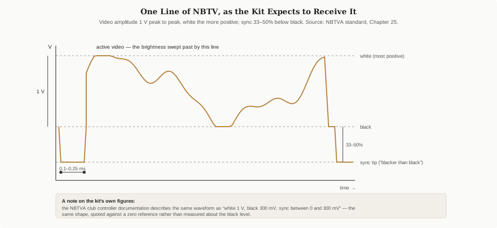
The sync pulses go somewhere the picture cannot follow. Between lines, the signal dips to a level 33% to 50% more negative than video black — a region the standard itself calls “blacker than black” or “ultra black”. No scene content, however dark, can reach that voltage, so a receiver watching for that excursion can identify a sync pulse unambiguously. Each pulse is brief: 0.1 to 0.25 milliseconds, which against a 2.5 millisecond line is four to ten per cent of the line period.
The signal is AC-coupled, and the standard is candid about the consequence: the black-level voltage floats up and down with the mean brightness of the picture. Receivers may use DC restoration or clamping to re-anchor it. This is not a defect to be engineered away; it is a property of sending a signal through capacitors, transformers, radio links and sound cards, all of which remove any steady component.
Frame sync is an omission. The one line-sync pulse that would fall between line 32 and line 1 is simply left out, and the video is held at black for that interval instead. A receiver counting pulses finds one missing and knows the frame has ended. There is no separate frame-sync signal, no distinct pulse shape, no second channel. Vol 2 describes how this kit realises that omission physically, by taping over one hole in the disc’s sync ring.
3.3.1 The improvement over Baird, stated plainly
The association’s standards page records something that deserves more attention than it usually gets. Baird never used ultra-black sync pulses at all. His system used an ordinary black bar between lines, at the same voltage as the darkest picture content. Because a genuinely black picture and a sync pulse were therefore electrically indistinguishable, his receivers could lose synchronisation whenever a scene went fully black — and so, in the association’s own words, black pictures were never permitted on the service.
A production constraint on what British television was allowed to show, for six years, imposed by a synchronisation limitation. The modern standard’s blacker-than-black region removes it entirely: an NBTV picture may go completely black with no risk whatsoever of the receiver losing its place.
3.3.2 Reconciling the kit’s own figures
The NBTVA’s documentation for its club televisor controller describes the same waveform in different words: “The white level is 1 Volt whilst the black is 300mV. Between zero and positive 300mV we see the regular synchronising pulses.” This is not a second standard. It is the identical waveform quoted against a zero reference rather than measured about the black level — white at 1 V, black at 300 mV, sync occupying the range below black down toward zero. The 1-volt video swing and the blacker-than-black sync region are both present; only the datum has moved.
3.4 Why Ten Kilohertz Changes Everything
The bandwidth figure — 2 Hz to 10 kHz at −3 dB — is the single most consequential number in the standard, because it is what makes an NBTV picture portable by ordinary means. Ten kilohertz sits comfortably inside what any audio equipment reproduces. A 44.1 kHz digital audio stream carries it with room to spare. A telephone-grade voice channel passes it with mild attenuation. A sound card’s line output delivers it without knowing or caring what it is.
For comparison, the same page notes that the Baird 30-line signal has a theoretical bandwidth of approximately 13 kHz — so the modern standard is, if anything, slightly narrower despite having two more lines.
One derived consequence is worth stating because it sets a ceiling on expectations. With at most 10 kHz available over a 2.5 millisecond line, roughly 25 cycles fit into one line, giving on the order of 50 resolvable elements along its length. The picture is therefore something like 32 lines by 50 elements — an estimate, not a standard figure, but a useful one. No amount of care in the source material will produce detail finer than that.

3.5 Getting the Signal In: Cables and Impedances
The standard specifies the physical interface too, which saves a certain amount of guessing:
- Cable: screened — phono cable or coax.
- Connector: phono / RCA type; female at equipment, male on cables.
- Colour convention: yellow, white or black for video; red for audio, in line with ordinary audio equipment practice.
- Output impedance: low — 500 ohms or less.
- Input impedance: high — 5 kilohms or more.
This is a line-level interconnect in every respect, which is why a hi-fi CD player’s line output is the association’s recommended source and why a headphone socket, with its different impedance and its low-frequency roll-off, is a compromise rather than an equivalent.
3.6 Storing and Sending It
Because the signal is audio, the question of how to store it becomes a question about audio media, and the association has firm recommendations.
Recommended: CD-R, CD-RW and DVD-Audio. Direct digital recording is almost free of waveform distortion, has ample bandwidth, and — critically — has crystal-stable playback speed, which matters enormously for a signal whose entire picture geometry depends on the receiver’s scan rate matching the rate the material was made at. The specified format is 44.1 kHz, stereo, 16 bits per sample: ordinary audio-CD parameters. Video goes on the left channel; sound or separate sync on the right. Recording level for the audio channel is −10 dB with peaks to −2 dB; the video channel should be set so that playback delivers a signal conforming to the video standard above. For files, the same parameters with a .WAV container.
Forbidden, in effect: MP3, WMA and other bit-rate-reduced formats. The standard is unambiguous, and the reasoning is exact: those algorithms discard whatever a psychoacoustic model predicts a listener will not notice, and that model has nothing whatever to do with what makes a picture legible. The distortion may be inaudible and will be visible as a noisy picture. A file can sound completely normal and be useless as a television source. Vol 4 returns to this because it is the single easiest way to waste an evening.
Tape is documented as historically workable but with no common standard; members overcame its limitations with pre-distortion, frequency correction, FM modulation and “negative time” distortion cancellation.
Radio, for members who transmit rather than play files, is specified in four modulation schemes:
Table 2 — Radio, for members who transmit rather than play files, is specified in four modulation schemes
| Mode | Polarity | Depth / deviation | Bandwidth |
|---|---|---|---|
| AM positive | White is the largest HF amplitude | 95% depth; sync at 15% of maximum | 20 kHz |
| AM negative | Sync is the largest HF amplitude | 90% depth; white at 10% of maximum | 20 kHz |
| FM | Positive — white highest frequency, sync lowest | 15 kHz deviation, sync to peak white | 35 kHz (three channels in the 12.5 kHz grid) |
| VSB | — | — | Roughly half of AM or FM |
3.7 The Digital Form: Proof There Is No Ambiguity
One section of the standard is easy to skip and worth reading, because it demonstrates that everything described qualitatively above has an exact, byte-level representation. For pattern generators built around EPROMs, the standard specifies 64 bytes per line; byte 00 is the bottom right of the picture, byte 63 (hex 3F) the top right, and the last byte (hex 7FF) the top left. Sync occupies the first three bytes of each line, with a set bit indicating sync; the sync bytes of the first line are zeroed, which is the missing pulse in stored form. File extensions encode the bit allocation — .P8 for 8-bit still pictures, .P7S for 7-bit stills with sync on bit 0, .V6D for video with delta-modulated audio in the low bits, .V5C for video with PCM audio.
The scan order in that specification — first byte bottom right, last byte top left — is the raster order from the table above, written out unambiguously. Anyone writing an encoder can check their line ordering against it.
3.8 What the Standard Does Not Say
Three honest gaps, recorded so that later volumes do not quietly invent answers:
- It says nothing about this kit. The standard defines a signal, not a receiver. Everything specific to the MindSets unit — its 6-volt supply, its R7 preset, its onboard test card — comes from the association’s handbook chapter on that kit and from builders’ accounts, not from here.
- It does not specify how a source should behave when it stops. Nothing in the standard describes what a receiver should do when the signal ends, which is precisely the situation a live source creates every time it stutters. Vol 5 treats that as an engineering problem to be solved by the source.
- The 2 Hz lower limit is aspirational on consumer hardware. The standard asks for response down to 2 Hz; ordinary AC-coupled sound cards and CD players do not deliver it. The association acknowledges this obliquely by recommending line outputs over earphone outputs and by publishing an amplifier specifically for earphone-output sources. The practical effect is on large-area shading, not on fine detail.
3.9 Cross-References
- How this kit’s electronics acts on the waveform described here — sync separation, the phase-locked loop, the physically missing pulse: Vol 2.
- Producing a conforming file from an ordinary video clip, and the polarity trap: Vol 4.
- Generating the waveform directly from a computer, including the sample-rate arithmetic the standard implies: Vol 5.
- The standard in its general and historical context, including why the club chose 32 lines rather than Baird’s 30: Vols 11 and 12 of the companion Mechanical TV Deep Dive.
- A side-by-side table of the Baird and NBTV standards: Vol 16 of that dive.
Comments (0)