Televisor Kit Build · Volume 7
The Steampunk Cabinet — a Plan, Not a Build
Nothing in this volume has been built. Not a joint cut, not a board bought, not a dimension confirmed against a physical object. The kit itself has not been assembled, and a cabinet for it cannot sensibly be started until the thing it houses exists and has been measured. What follows is design intent: the reasoning behind a set of choices, the constraints those choices have to satisfy, and an explicit list of the decisions still open. Every dimension below is derived from the manufacturer’s published chassis size plus clearance, and every one of them should be checked against the assembled kit before any timber is cut.
The volume is written now rather than later because the useful part of cabinet design is the thinking, and the thinking is worth recording while the constraints from Vols 2 and 3 are fresh: the disc must come out, the disc must be guarded, the motor must not be sealed into a box with its own noise, and the picture is faint enough that stray light is a genuine enemy.
7.1 Why a Cabinet at All
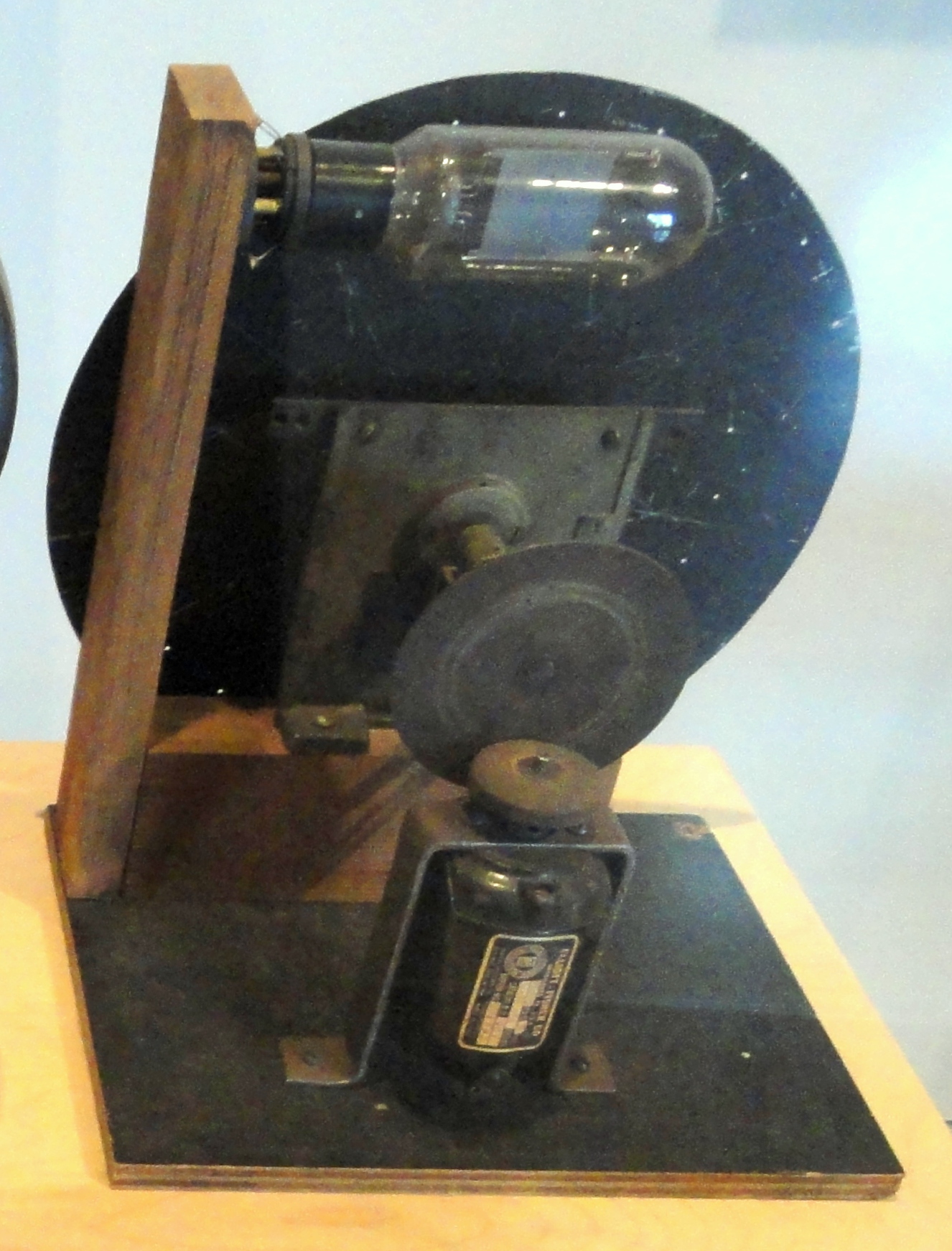
The kit as supplied is a plastic chassis styled as a miniature of Baird’s Televisor. It works, and it looks like what it is: a modern educational kit.
The case for building something around it is one the NBTVA itself makes, in the plainest terms, in its beginner’s construction chapter: the original Baird televisors were constructed as a piece of furniture, and a builder may well wish to produce some elegant cabinetwork to house their own. That is the tradition this design joins. A mechanical television was a domestic object before it was a museum piece — a thing that sat in a room with other furniture and was expected to look as though it belonged there.
7.2 What “Steampunk” Should Mean Here
There is a real risk in this brief, and it is worth naming before the design rather than regretting it after. Steampunk as a decorative style collapses easily into applied ornament — cogs glued to surfaces they do not turn, gauges that measure nothing, pipes that carry nothing. Applied to a machine that genuinely does have a spinning disc, a genuinely Victorian-descended operating principle and a genuinely nineteenth-century patent behind it, that would be a peculiar waste.
The governing rule adopted here is therefore: every brass element does a job. A bezel frames the viewing aperture. A grille covers a ventilation opening. A knob turns something. A corner strap protects a corner. A hinge hinges. Nothing is added because it looks like it might be Victorian.
There is also an honesty problem worth stating, because this dive’s voice does not permit pretending otherwise: the object inside the cabinet is a 2020s plastic kit with surface-mount components and an LED. A mahogany-and-brass case is a costume, not a restoration. That is a perfectly good reason to build one — it is also a reason not to age the brass artificially, fake a maker’s plate, or present the result as anything other than what it is.
7.3 Dimensions and Layout
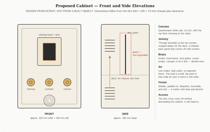
The kit’s published chassis size is 260 × 195 × 70 mm. Adding clearance for the cabinet walls, the viewing hood, the disc guard, cable runs and a hand, the working proposal is:
Table 1 — The kit's published chassis size is 260 × 195 × 70 mm. Adding clearance for the cabinet walls, the viewing hood, the disc guard, cable runs and a hand, the working proposal is
| Dimension | Proposed | Reasoning |
|---|---|---|
| Width | approx. 320 mm | Chassis width plus wall thickness and side clearance for cabling |
| Height | approx. 420 mm | Deck at mid-height, hood and disc above, controls and speaker below |
| Depth | approx. 280 mm | Chassis depth plus hood depth plus rear connector clearance |
| Material thickness | 16 mm | Stable in a carcase this size; adequate for dovetailed corners |
The layout puts the kit chassis on a fixed deck at mid-height, the disc plane vertical and behind the front panel, the viewing hood and lens on the front face at eye level when the set is on a table, and the controls and a speaker grille below. Connectors go on the back.
7.4 Carcase and Joinery
Quartersawn white oak, 16 mm, is the proposed carcase material. Quartersawing exposes the medullary rays as the characteristic fleck across the board face, which is both the traditional look for furniture of the relevant period and — as the finishing section below explains — the feature that responds most dramatically to fuming. Walnut and mahogany are reasonable alternatives with a more restrained figure.
The joinery proposed is deliberately visible:
- Through dovetails at the top corners. Strong, appropriate to the period, and honest — the joint shows on the outside and says what it is.
- Stopped dados for the deck. The shelf carrying the kit chassis is structural, tying the sides together at mid-height, and a stopped dado hides its housing from the front.
- A rebated back panel, screwed rather than glued. Non-negotiable. Everything inside will need attention again.
- A lift-off or hinged top. The single most important access decision, and the reason for it is the disc.
7.4.1 The disc must come out
Builders of this kit report discs arriving around two millimetres off centre, with a curl, and occasionally separating from the hub because the adhesive is inadequate. Beyond those faults, the sync-hole tape has to be repositioned by trial during commissioning (Vol 2), and the disc’s clearance to the sensor and to the board matters.
A cabinet that requires dismantling to reach the disc is a cabinet that will be dismantled, repeatedly, badly. The design constraint is stated as a requirement rather than a preference: the disc and its hub must be reachable and removable without taking the carcase apart — via a hinged or lift-off top, with the disc slot in the deck sized to let the disc pass.
7.5 The Guard
The NBTVA’s own construction literature does not soften this, and neither does this volume:
“A high-speed spinning disk is inherently dangerous and may cause serious injury if accidently touched during operation. The NBTVA strongly advise that a protective cover is fitted around the disk to avoid accidents.”
That warning is written for the association’s larger 12-inch club designs, and this kit’s disc is considerably smaller. The principle is unchanged: at 12.5 revolutions per second — 750 rpm — the rim is moving fast enough to injure, and an open disc inside a domestic cabinet is within reach of anyone who opens the lid while it is running.
Two options, with a genuine trade-off:
- A brass mesh or perforated grille. Visually right, ventilates by itself, and obscures the disc — which matters if the disc is meant to be part of the appeal.
- A glazed panel in a brass frame. Keeps the disc visible, seals that face (so ventilation must be handled elsewhere), and is honest about being a modern safety addition.
The glazed brass-framed panel is the current preference, for visibility. Whichever is chosen, it should be interlocked with the lid in intent if not in mechanism: opening the top should be a deliberate act performed with the set switched off.
There is a second, less obvious hazard already noted in Vol 1: the ultra-bright LEDs used in NBTV monitors are, in the association’s own words, strong enough to injure eyes if viewed without a diffuser. The cabinet must not create a sight line to the bare lamp — which it will not, if the lamp box is enclosed and the only view of it is through the disc and the hood.
7.6 The Viewing Hood
The hood has one job: keep room light off the lens so it does not compete with a picture that is, in absolute terms, extremely faint (Vol 2). The association’s own construction notes call for a black viewing tunnel to prevent surrounding light falling on the glass and causing reflections.
Design consequences:
- Matt black inside, completely. Not dark paint, matt black — flocking paper or blackboard paint. Any sheen inside the hood defeats its purpose.
- Depth is a trade. A longer hood excludes more light and shrinks the eye box; a shorter one is easier to look into and works less well. Somewhere around 60–80 mm is the usual compromise in club builds and should be treated as a starting point to be tested, not a specification.
- The brass bezel goes on the outside and should not intrude into the light path.
- The lens is the kit’s own. Its focal length sets the distance from disc to lens and from lens to eye, so hood depth is constrained by the kit rather than chosen freely. This is one more dimension to measure before cutting.
7.7 Ventilation — for the Right Reasons
It is worth being honest about the thermal load: it is small. A 6-volt motor and a handful of LEDs do not generate meaningful heat, and a cabinet of this size will not cook anything. Anyone who tells you this design needs ventilation for cooling is repeating a general rule without checking it.
The reasons vents are still in the design are different, and better:
- A motor should not be sealed in with its own dust. Brushed motors shed brush dust. Sealed in a box with a spinning disc stirring the air, that dust lands on the disc, on the diffuser and on the optical sensor — and the sensor’s job depends on a clean optical path.
- A spinning disc moves air. A disc turning at 750 rpm inside a closed wooden box is a small centrifugal fan inside a resonant cavity. Openings let that air out instead of letting it circulate and drum.
- Sound. Some acoustic transparency makes the motor note audible, and the motor note is a diagnostic — Vol 2 notes that lock is audible before it is visible.
The arrangement follows from that: low intake and high outlet, on opposite faces, behind brass grilles, sized generously rather than minimally. There is no fan and no need for one.
7.8 Brass
The brass elements in the design are the hood bezel, the vent grilles, the control knobs, corner straps if the carcase wants protecting, and the lid hinge. All working parts.
One decision has to be made once and then adhered to: lacquer the brass, or let it patinate. Lacquered brass stays bright and eventually chips, after which it looks worse than either alternative. Unlacquered brass dulls to a soft brown and can be polished back when the mood takes. What looks wrong is a mixture — some pieces bright, some dull — which is what happens by default when the decision is not made deliberately. Given that the cabinet will be handled at the lid, the knobs and the hood, and that handled brass patinates fastest, the honest choice is probably unlacquered and allowed to age.
7.9 Finishing
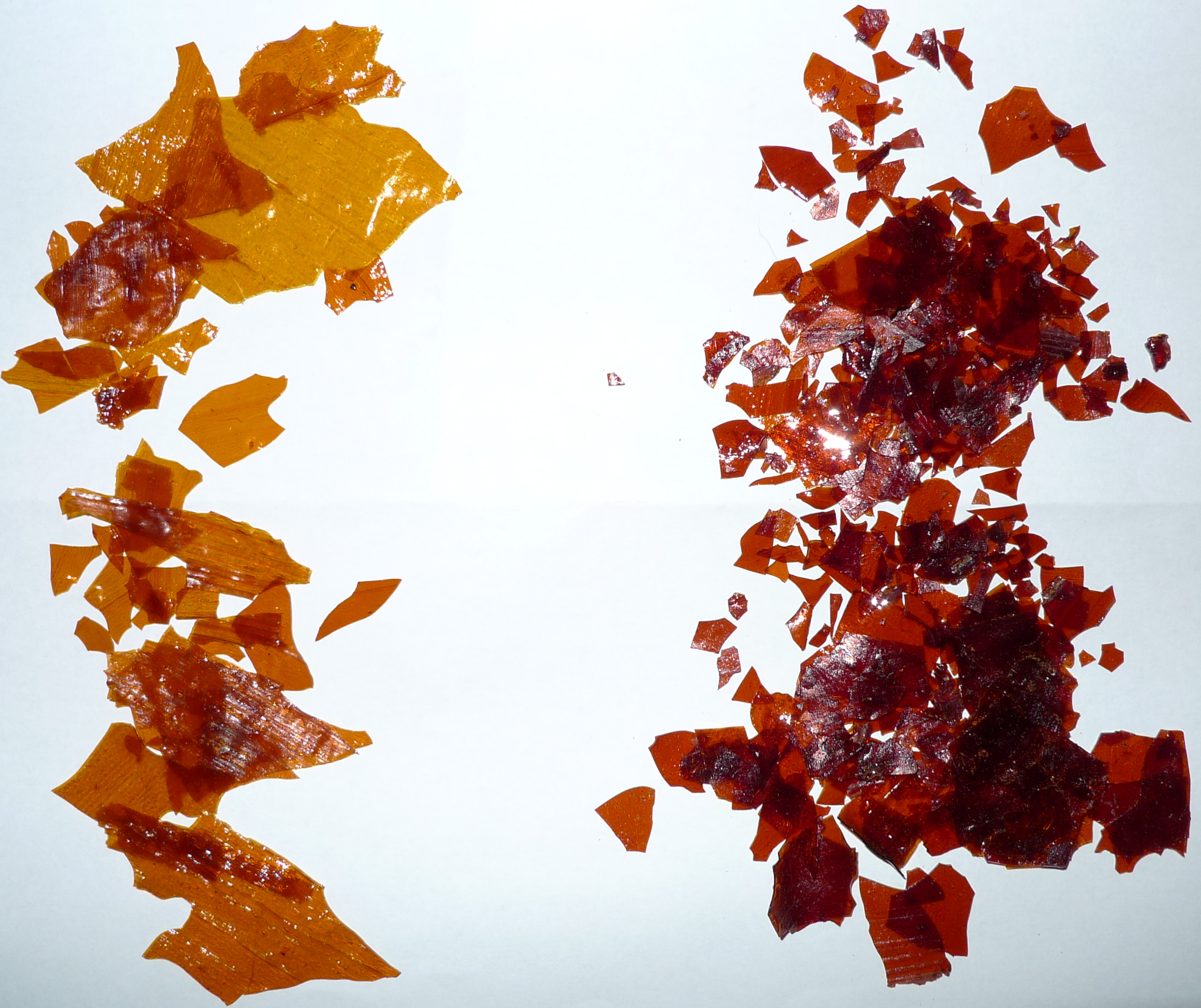
Shellac, padded on, is the proposed finish — the traditional approach for furniture of this period, applied as a French polish: many thin coats of shellac dissolved in alcohol, applied with a rubbing pad lubricated with oil. It builds quickly, has extraordinary depth on quartersawn oak, is entirely reversible with alcohol, and is the finish the originals would have worn.
Its weaknesses must be designed around rather than discovered:
- It marks with heat. A hot object set down without a mat leaves a burn. Relevant here mainly because the cabinet’s top is a flat surface at table height and will be used as one.
- It marks with water and with alcohol. Spills produce white cloudy blooms. A drink set on top of a shellacked cabinet is a repair job.
- It is softer than modern varnishes and lacquers.
All three are repairable — that is shellac’s compensating virtue; a damaged area can be re-amalgamated with alcohol rather than stripped. A builder who would rather not think about it should use an oil-varnish blend instead and accept a less luminous surface.
7.9.1 Fuming: optional, effective, and genuinely hazardous
Ammonia fuming darkens white oak from the inside: the fumes react with tannins in the wood and change its colour permanently, and because the medullary rays contain less tannin than the surrounding wood, they stay lighter — so the fleck exposed by quartersawing is thrown into strong contrast. It is the classic treatment for oak of this era and it produces a colour no stain reproduces convincingly.
It is also the most dangerous operation in this entire dive, and by some distance. The ammonium hydroxide used for fuming is around 28% ammonia, against under 5% in household ammonia. It is not a stronger version of a cleaning product; it is a different hazard class. Minimum precautions, from the woodworking literature: a respirator with cartridges rated specifically for ammonia (ordinary charcoal vapour filters reduce exposure but are not adequate on their own), sealed goggles or a full face shield, chemical gloves, and a tent or chamber outdoors or in genuinely open ventilation, never in an occupied building.
It is entirely optional. The cabinet works without it.
7.10 Mounting, Wiring and Controls
Three practical points drawn from what builders report about this kit:
Isolate the motor mechanically. The motor is brushed, and forum reports describe its supply showing wild fluctuations, ripple and spikes from brush arcing and inductive kickback. Mechanically, a rigidly bolted motor transmits vibration into a wooden box that will amplify it. Compliant grommets at the kit’s mounting points cost nothing and address both the noise and, indirectly, the disc’s stability.
Separate signal wiring from motor wiring. The same brush noise couples electrically. The run from the input connector to the board carries a low-level signal into a high-impedance input; it should be screened, short, and routed away from the motor leads rather than bundled tidily alongside them. Tidy and correct are not the same thing here.
Think twice before extending presets to panel controls. It is tempting to bring the board’s amplitude preset (R7, Vol 2) out to a brass knob on the front. The downside is real: a preset is a high-impedance node, and running long leads from it to a panel invites exactly the noise pickup the previous paragraph is trying to avoid. The controls shown on the front elevation are drawn as framing, contrast and volume by analogy with the association’s own club design, which has them — whether this kit exposes equivalent adjustments at all is an open question below.
Connectors on the back, to the standard. Phono/RCA sockets for the NBTV input, per the association’s interconnect convention (Vol 3), on a removable back panel.
7.11 Open Decisions
Recorded so that they are decided deliberately rather than by default:
- Timber — quartersawn white oak, walnut, or mahogany.
- Fumed or not — a real choice with a real hazard attached.
- Guard type — brass mesh, or glazed panel in a brass frame.
- Brass finish — lacquered or left to patinate.
- Hood depth — constrained by the kit’s lens, to be determined by test.
- Top access — hinged or fully removable.
- Whether any controls reach the front panel at all, which depends on what the kit actually exposes.
- Speaker and audio — whether to include the audio channel’s reproduction in the cabinet, which the club’s own designs do and this kit may not support.
7.12 Cross-References
- The mechanical and optical constraints the cabinet has to respect — disc access, lamp enclosure, sensor cleanliness, hood function: Vol 2.
- The interconnect convention the rear panel should follow: Vol 3.
- The commissioning steps that require the disc to be reachable, repeatedly: Vol 8.
- Baird’s own Televisor as a piece of furniture, and how the originals were cased: Vol 6 of the companion Mechanical TV Deep Dive.
- Restoration and building practice for disc televisors in general, including safety: Vol 15 of that dive.
Comments (0)