Televisor Kit Build · Volume 8
Commissioning, Reference and Open Questions
This volume is the one to have open on the bench. It collects the commissioning order, the failure modes other builders have already found and published, the reference numbers scattered through the preceding volumes, and — at the end, at length — an honest account of what this dive does not know.
Two framing notes. First, the kit documented here has not been built, so nothing below is a report of what happened; it is a plan assembled from the association’s own fault-finding literature and from builders’ published accounts. Second, the association’s detailed fault-finding chapter was written for its laser-cut club televisor, a larger and different machine — a 12-inch disc, a 16-volt supply, an internal media player. Its principles transfer directly and its component references do not. Where a specific designator appears below it is flagged with which machine it belongs to.
8.1 The Commissioning Order
The order matters more than any individual step. Each stage depends on the one above it, and the commonest way to waste an evening is to chase a picture before the sync pulses are clean.
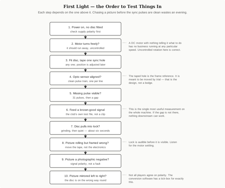
1. Power on with no disc fitted. Confirm supply polarity before anything else. Four AA cells, 6 volts nominal.
2. Confirm the motor turns freely and uncontrolled. This looks like a fault and is not. A brushed DC motor with no signal telling it what speed to run has no reason to run at any particular speed (Vol 2). Uncontrolled rotation at this stage is the correct result; controlled rotation at this stage would be surprising.
3. Fit the disc and tape over one sync-ring hole. Any one of the 32. Its position determines where the picture sits horizontally and is adjusted later by trial, so do not agonise over the choice. Black insulating tape is what the association’s guide specifies.
4. Align the optical sensor. Position it to read the sync ring cleanly. The association’s guide for its own machine describes using a digital camera or phone camera to see the infra-red emitter’s glow through the synchronising holes while rotating the disc by hand — a genuinely useful trick, since the emitter is invisible to the eye. It notes one exception: iPhones filter infra-red and will not show it.
5. Confirm the pulse train, with the missing pulse. On an oscilloscope this is a regular stream of pulses with a missing pulse every thirty-one. This single observation validates the disc, the sensor, the alignment and the tape position simultaneously. It is the most informative measurement on the machine and everything after it assumes it.
6. Feed a known-good signal. The kit’s own CD, or the association’s demonstration wave file (Vol 4) — not a home-made clip. A conversion error and a hardware fault produce overlapping symptoms, and the only way to tell them apart is to eliminate one.
7. Confirm lock. Expect a twitch at switch-on, spin-up as pulses arrive, an audible grinding as the loop closes, and settling at a mean of about six seconds, worst case a little over twelve, on the association’s own controller. Lock is audible before it is visible.
8. Frame the picture. If it locks but sits wrongly in the window, move the tape to a different sync hole. This is a geometry adjustment, not an electrical one.
9. Check polarity. A photographic negative — dark subjects bright, bright subjects dark — is a polarity problem in the playback chain, not a fault (Vols 3 and 4).
10. Check handedness. A picture wound the wrong way left to right means the disc is facing the wrong way round.
8.2 Known Failure Modes
Collected from the NBTVA forum’s discussion of this specific kit, a vintage-television forum thread on it, and the association’s own fault-finding guide. None of these was observed here; all are reported by others.
Table 1 — Known Failure Modes
| Symptom | Reported cause | Remedy |
|---|---|---|
| Disc wobbles; sensor output amplitude wanders | Disc arrives around 2 mm off centre, or with a curl; must run almost flat and at a consistent distance from the sensor | Re-seat on the hub; check flatness before fitting |
| Disc parts from its hub | Inadequate adhesive as supplied | Re-bond properly before commissioning |
| Disc fouls the board | Insufficient running clearance | The disc must not touch the PCB anywhere in rotation |
| Sync disc fouls the sensor | The paper “stroboscope” disc rubbing | Keep it clear of the opto sensor |
| Noise and instability in sync | Brushed motor: ripple and spikes from brush arcing and inductive kickback coupling into the sync circuits | Screened, short, separated signal wiring (Vol 7) |
| No lock; rolling picture | Signal amplitude wrong | Adjust the amplitude preset — R7 on this kit, per forum discussion |
| Impaired large-area shading | Source is an earphone output, good only to about 20 Hz where the standard asks 2 Hz | Use a line output |
| Negative picture, or sync misread as picture | Signal polarity inverted relative to what the board expects; the kit’s own CD reportedly carries both polarities | Use the other polarity, re-convert with the inversion option, or swap the two signal wires on a battery-operated set |
| Inverted picture (club machine) | Motor cables transposed | Transpose them back |
| Picture mirrored left to right | Disc facing the wrong way round | Turn it over |
| Runs too fast; framing control lacks range | Reported on the newer hardware revision | No published fix located; see open questions |
| Vertical framing exactly half a frame out | Top and bottom of the picture meeting in the middle | Move the taped sync hole |
| Only the onboard test card displays | Fault is in the input chain, not the display | Work backward from the input socket; the display is proved |
That last row is worth its own sentence. This kit has an onboard test card, which means the display side can be proved independently of any external signal. If the test card appears and external material does not, every component from the lamp through the disc to the lens is working, and the problem is the signal, the cable, the level or the polarity. Few pieces of hobby equipment bisect their own fault space so conveniently.
8.3 Reference Tables
8.3.1 The standard, as verified
Table 2 — The standard, as verified
| Parameter | Value |
|---|---|
| Lines per frame | 32 |
| Frames per second | 12.5 |
| Lines per second | 400 |
| Line scan | Vertical, bottom to top |
| Frame scan | Horizontal, right to left |
| Aspect ratio | 3 : 2, portrait |
| Rotation / viewing side | Anti-clockwise / right |
| Video amplitude | 1 V peak to peak |
| Video polarity | White more positive |
| Bandwidth | 2 Hz – 10 kHz at −3 dB |
| Sync level | 33–50% more negative than black |
| Line pulse width | 0.1 – 0.25 ms |
| Frame sync | Pulse omitted between line 32 and line 1; video black |
| Coupling | AC; DC restoration permitted |
| Connectors | Phono/RCA on screened cable; source ≤ 500 Ω, input ≥ 5 kΩ |
| Recording | 44.1 kHz, 16-bit stereo; video left, audio right; audio −10 dB, peaks −2 dB |
8.3.2 Derived numbers
Table 3 — Derived numbers
| Quantity | Value | From |
|---|---|---|
| Frame period | 80 ms | 1 ÷ 12.5 |
| Line period | 2.5 ms | 1 ÷ 400 |
| Disc speed | 750 rpm | 12.5 rev/s × 60 |
| Aperture angular pitch | 11.25° | 360° ÷ 32 |
| Samples per frame at 44.1 kHz | 3,528 exactly | 44,100 ÷ 12.5 |
| Samples per line at 44.1 kHz | 110.25 — not an integer | 3,528 ÷ 32 |
| Sync pulse at 44.1 kHz | approx. 4–11 samples | 0.1–0.25 ms |
| Approximate horizontal resolution | roughly 50 elements | 10 kHz over a 2.5 ms line |
8.3.3 The kit
Table 4 — The kit
| Item | Value | Source |
|---|---|---|
| Product | MindSets Online “Televisor”, code NMP-003 | Vendor listing |
| Price | £53.94 inc VAT (£44.95 ex) | Vendor listing |
| Assembled size | 260 × 195 × 70 mm | Vendor listing |
| Power | 4 × AA (6 V nominal) | Vendor listing |
| Display | Spinning Nipkow disc, 32 apertures, LED source | Vol 1, four independent sources |
| Sync | Opto sensor on a 32-hole ring, one hole masked; CD4046 PLL | NBTVA forum |
| Input | Line level, per club standard | NBTVA forum, vendor listing |
| Supplied media | Audio CD, approx. 25 minutes of 32-line NBTV | Vendor listing, NBTVA |
| Lineage | Formerly the MUTR Televisor Kit | NBTVA news page |
8.4 Safety
- The spinning disc. 750 rpm. The association’s construction literature states without qualification that a high-speed spinning disc is inherently dangerous and may cause serious injury if accidentally touched during operation, and strongly advises a protective cover. Vol 7 treats a guard as a requirement.
- The lamp. Ultra-bright LEDs of the type used in NBTV monitors are, in the association’s own words, strong enough to injure eyes when viewed without a diffuser. Do not run the lamp box open.
- Ammonia fuming, if the cabinet is fumed, is the most hazardous operation in this dive: roughly 28% ammonium hydroxide, requiring ammonia-rated respirator cartridges, sealed eye protection, gloves and genuine open ventilation. Optional, and the cabinet works without it.
8.5 Open Questions
Ten things this dive could not establish. Each is a specific, answerable question rather than a general caveat.
- The NBTVA handbook’s own chapter on this kit was not read. Chapter 10, “MUTR miniature Televisor kit”, is listed in the handbook contents but is not among the chapters published on the open web; it is in the purchasable printed handbook. It is almost certainly the best single description of this machine in existence. Resolve by: buying the handbook, or joining the association.
- The
nbtv-design-toolsarchive was not opened. SourceForge refuses automated clients on every download path (Vol 5). The per-tool detail and the hardware design example insidenbtv-design-and-tools.pdfare consequently absent from this dive. Resolve by: downloading the 36.6 MB V1.4 archive manually in a browser. video2nbtvwas not installed or run. It is a Windows binary, preserved on the Internet Archive; the builder’s machine runs Linux. Whether it runs acceptably under Wine is untested. Resolve by: trying it.- The free
.wavdownloads of this kit’s CD could not be located. The association’s news page states the files can be downloaded freely from its website and links a directory that returned HTTP 404, as did several address variants. Resolve by: asking the association via its contact page. - Which hardware revision will arrive is unknown. Two are documented — an older board with conventional components standing clear of the motor board, and a newer one with surface-mount parts moved to the disc side. The reported sync-too-fast problem attaches to the newer one. Resolve by: photographing the board on arrival and comparing.
- The disc’s actual diameter and aperture dimensions are not published for this kit, and must not be assumed from the association’s 12-inch club disc — the whole chassis is only 260 mm wide. Resolve by: measuring, and recording the figures here.
- Motor current draw is unknown. The 6-volt nominal supply is published; the current is not, which matters for anyone considering a mains supply in place of cells. Resolve by: measuring.
- The nature of the onboard test card is ambiguous. Builders describe an “onboard test chart”, which could be an electronically generated pattern or a physical printed card illuminated behind the disc. These have quite different diagnostic value. Resolve by: looking.
- The input connector type is unconfirmed. The standard specifies phono/RCA; the vendor says only that it plugs into a CD player. Whether the kit presents phono sockets, a 3.5 mm jack or a flying lead is not established. Resolve by: looking, and buying the right adapter in advance if possible.
- The reference build’s video was not viewed. Vol 6 rests on the Hackaday article’s account of smill’s work rather than on the video itself, which the research tooling used here could not read. Resolve by: watching it.
8.6 What Happens Next
In order, when the kit arrives:
- Photograph the sealed box, then the contents laid out, then the disc against a light, then the bare board — before assembling anything (Vols 1 and 2 carry the slots).
- Measure and record the six unknowns above that a rule and a meter will settle.
- Assemble, then commission in the order set out at the top of this volume.
- Prove the display with the onboard test card, then with the kit’s own CD, then with the association’s demonstration wave file, and only then with home-made material.
- Convert a first clip (Vol 4) and photograph the source frame and the disc frame together.
- Build the live path (Vol 5) — starting with a generated test pattern, not a picture.
- Mock the cabinet up full size in cheap material before cutting timber (Vol 7).
Sources
Primary — the NBTVA (nbtv.wyenet.co.uk): Chapter 25, “NBTV standards and recommendations”; Chapter 4, “Building a complete NBTV disc televisor”; Chapter 3, “Typical NBTV equipment”; the handbook contents listing; the “Hot News” page identifying the kit’s MUTR lineage; the “sound of NBTV” page and its demonstration wave file; the Club CD Number One page; and the laser-cut televisor construction guide, Chapters 1–11, by James Sheehan and Chris Lewis, including the control-board notes crediting Peter Smith’s LED driver and sync separator and Karen Orton’s PIC motor drive.
The kit: the MindSets Online product listing (mindsetsonline.co.uk/shop/televisor/); the Grand Illusions listing of the same kit.
Builders: the NBTVA forum thread on the Mindsets Televisor (taswegian.com/NBTV/forum, topic 3046), including contributions from Klaas Robers; the Videokarma thread on the Mindset “Televisor” kit (topic 276340).
Tooling: video2nbtv by Gary Millard, preserved at archive.org/details/video2nbtv and archive.org/details/video2nbtvinstallv3; nbtv-design-tools by vincent95 at sourceforge.net/projects/nbtv-design-tools/.
Reference build: Hackaday, “CRTs Are Too Mainstream, So Game On A Mechanical TV Instead”, 12 May 2026, and the comment correcting its frame-rate figure.
Comparative build detail: LabGuy’s World, “NBTV — Big 32 Line Televisor Project”, for disc, LED-drive and CD4046 practice on a larger machine.
8.7 Cross-References
- What the kit is, and the evidence that it is a genuine disc machine: Vol 1.
- The mechanism behind every step of the commissioning order: Vol 2.
- The standard the reference tables summarise: Vol 3.
- Conversion, and the known-good material to commission with: Vol 4.
- Live driving and encoder design: Vol 5.
- The reference build and the frame-rate correction: Vol 6.
- The cabinet plan the last open decisions belong to: Vol 7.
Comments (0)