Mechanical TV Deep Dive · Volume 15
Restoration & Building
Every volume in this series up to this point has been written from the outside looking in: how the Nipkow disc scans a picture, how the Baird Televisor was built, what a genuine one costs, why the modern NBTV standard settled on 32 lines instead of 30. This volume is written from the workbench looking out. There are, honestly, only two roads that lead from “I have read about mechanical television” to “I am watching a picture assemble itself line by line in front of me,” and neither of them is a shortcut. The first road runs through a genuine or partial period set — a Baird Televisor, or the disc, motor, and lamp salvaged from one — approached as an act of conservation rather than repair, because what survives is scarce, fragile, and in places genuinely lethal to work on carelessly. The second road runs through the modern hobby the NBTVA has spent half a century refining: a pre-cut disc, a small motor, a cluster of LEDs, and a sync circuit, all buildable on an ordinary bench from parts costing a few tens of pounds. Both roads are honest, both are documented, and both end at the same reward — a spinning disc, a glowing display, and a picture that should not, by any reasonable expectation of 21st-century electronics, still work this way. This volume takes safety first, because a heavy disc at speed and a decades-old mains-powered chassis are real hazards and not narrative colour, and then walks each road in turn: what to do (and pointedly, what not to do) with a genuine set, and how to build a working receiver from nothing.
15.1 Two Honest Paths to a Working Set
The choice between restoring and building is not really a choice between “easy” and “hard,” or between “authentic” and “modern” — it is a choice between two different kinds of project with two different kinds of risk, and a reader should pick deliberately rather than by default. Restoring or conserving an original or partial period set starts from something Vol 14 already established in unsparing terms: a genuine, complete Baird Televisor is a five-figure rarity that has changed hands publicly only three confirmed times in the last fifteen years, and even the loose parts of one — a period disc, a period neon lamp, period synchronising hardware — turn up occasionally rather than reliably. A reader on this path is far more likely to be working with a partial set, a set of period-adjacent components, or a single genuine artefact (a disc, a lamp) bought to display or carefully bring back to life, than a complete working receiver bought outright. The work here is conservation-minded restoration: assessing condition without doing damage, understanding what is safe to touch and what is not, and knowing when to stop and call in someone more competent — because the specific hazards involved (addressed in full in the next section) are not hypothetical.
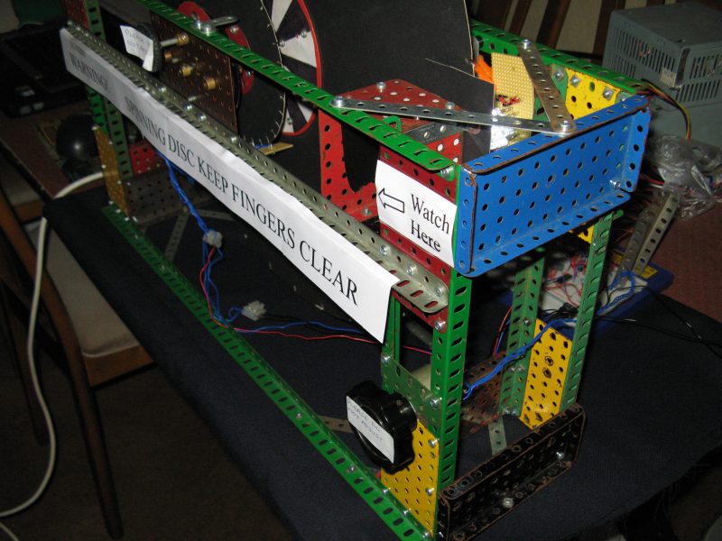
Building a working Nipkow-disc receiver from scratch starts from the opposite end: nothing period at all, just the NBTVA’s own decades-refined modern-parts path — a numerically machined disc, a small low-voltage DC motor, an LED light source, and a purpose-built sync circuit, most of it available directly from the club’s own Club Sales operation (Vol 11, §8c) for a total cost in the tens of pounds rather than the thousands. This is, for the overwhelming majority of people who want the experience of watching a scanning-disc picture rather than the specific object of a 1930s Televisor, the realistic and repeatedly-proven route — precisely the conclusion Vol 14 reached when it surveyed what actually turns up for sale. Nothing about this path requires mains wiring, high voltage, or a genuine period artefact; its hazards are real but much smaller in both scope and consequence than the restoration path’s, and are addressed alongside them below.
Most readers of this volume will, in practice, walk both roads eventually, in whichever order circumstances dictate: a modern build first, to learn what a working scanning-disc receiver actually looks and behaves like before risking anything genuinely old and irreplaceable, or a genuine partial set acquired first (an inherited disc, an auction lot of loose parts) that then sends its owner to the modern hobby’s documented electronics to make it work again. Either order is legitimate. What is not legitimate, and what this volume argues against directly, is skipping the safety discussion that follows in order to get to either project faster.
15.2 Safety First
Two genuinely different hazard classes are in play here, and they map cleanly onto the two paths above, so it is worth being explicit about which hazard belongs to which project before describing either one in detail.
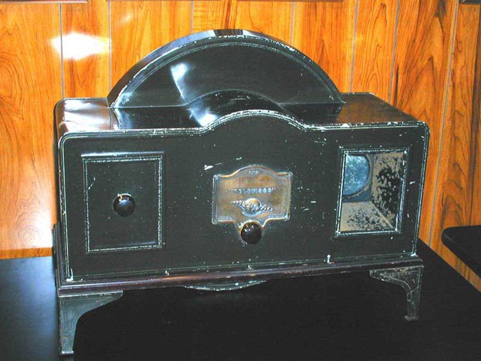
If the project involves a genuine or partial period set, the dominant hazard is mains electricity, not the disc. The Baird Televisor and its period contemporaries were built to what electrical engineers today call a “live chassis” design — the metal chassis is connected directly to one side of the incoming mains supply, rather than being isolated from it by a mains transformer, which is standard practice in almost all modern equipment. Experienced vintage-electronics restorers put this plainly: such equipment “as they are wired from the factory” is “deadly dangerous,” and a set should not even be plugged in until its wiring has been checked and, where necessary, made safe by someone who understands what they are looking at. Three specific things make period mains equipment more dangerous than it looks: first, mains-plug polarity in this era of equipment “usually had little effect with AC mains operation but could result in the chassis being LIVE” if wired the wrong way round — meaning a set can appear to work perfectly normally while its chassis, and everything metal touching it, carries full mains voltage; second, decades-old cloth-covered mains flex and perished rubber or cloth insulation on internal high-voltage leads are a real, confirmed hazard in surviving equipment of this age, not a theoretical worst case; and third, some period circuits generate their own internally stepped-up high voltage (EHT) for other purposes, and the UK preservation community’s own documentation describes mains-derived EHT of this vintage as “lethal” and capable of delivering “enough current to kill,” requiring the equipment to be unplugged and its capacitors deliberately, safely discharged — never assumed dead just because the mains lead is out of the wall, since capacitors can hold a dangerous charge long after power is removed. The recommended protection, per the same UK source, is a double-wound mains isolating transformer with an adequate insulation rating (which breaks the direct electrical link between the set’s live chassis and the household earth a person is standing on) plus a residual-current-device (RCD) protector — and, as a quick before-you-touch-anything check, a neon test-screwdriver held with the other hand kept well clear, to establish whether a chassis is actually live before assuming it is safe. None of this is a job to improvise. If there is any doubt at all about a genuine period set’s internal wiring, the honest and repeatedly-stated advice from people who do this professionally is to stop and get it checked by someone competent before applying power — not to guess.
If the project is a modern from-scratch build, the dominant hazards are mechanical and optical, both genuinely documented by the NBTVA’s own literature rather than invented here. A Nipkow disc spinning at the speed needed to reconstruct a 12.5-frames-per-second picture — one full disc revolution per frame, so 750 revolutions per minute for either the historical Baird 30-line standard or the modern 32-line club standard — is a rigid disc with an unguarded rim moving fast enough to cause a real cut or impact injury to a finger, a sleeve, or loose hair that strays too close, and the NBTVA’s own beginners’ construction chapter says so directly, if briefly: “take particular safety precautions with the spinning disc.” A hobbyist build’s spinning disc should be physically shielded from casual contact — a frame, a hood, or simply careful placement well clear of where hands naturally rest — and never touched, adjusted, or reached past while it is turning under power. Separately, and just as directly documented, the high-brightness LEDs the club specifically recommends for the light source — the AlInGaP “ultra-bright” type favoured for their close match to the historic neon glow — carry a manufacturer eye-injury warning: the NBTVA’s own text states plainly that “these LEDs carry warnings as the output light is strong enough to injure eyes when viewed without a diffuser.” This is precisely why the diffuser described later in this volume is not an optional cosmetic touch but a required safety component of the light source, to be fitted and correctly positioned before the LED cluster is ever run at full brightness with a person’s eye anywhere near its beam path.
Both hazard classes share one underlying rule worth stating on its own: know which project is in front of you before touching anything live or spinning. A genuine period set and a modern club build look, at a glance, like versions of the same object, but their actual danger profiles are almost entirely different, and treating a live-chassis period receiver as if it were as forgiving as a 12-volt hobby build — or, less commonly, panicking about mains danger on a battery-powered modern build that has none — is exactly the kind of category error this section exists to prevent.
15.3 Restoring or Conserving an Original: Ethics, Assessment, and Restraint
A genuine period set or a genuine period part is, almost by definition, one of a very small surviving population — Vol 14 documented that as few as around twenty of one Baird pre-production model were ever built, in 1928, and the great majority of what survives from the era sits in institutional collections rather than private hands. That scarcity changes the ethical calculus of restoration compared with, say, restoring a common 1970s radio: a mistake here is not just a wasted evening, it can be an irreversible loss to a small surviving record. The general standard the professional conservation field applies to exactly this situation — stated by the American Institute for Conservation’s own Code of Ethics, written for museum-grade conservation work generally, not for mechanical television specifically, but directly applicable here — is built around three ideas worth adopting wholesale for a genuine Televisor or period part: minimal intervention (do the least that achieves a stable, safe, presentable result, not the most); reversibility (prefer changes that can be undone, so a future, more capable restorer is not permanently boxed in by today’s decision); and the explicit acknowledgement that sometimes the right professional recommendation is no treatment at all — leaving a fragile original alone, fully documented, rather than intervening and risking damage.
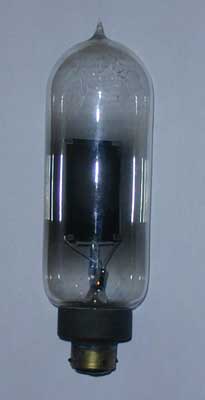
A real, documented example of exactly this ethic applied to genuine Baird-era hardware comes from the Early Television Museum’s own restoration of its Televisor, serial number 717. The museum’s account is plain about the problem: “neon tubes have a limited life,” and the set’s original neon display lamp — the flat-electrode glow lamp behind the Nipkow disc, the same component Vol 6 and Vol 13 describe in general, hedged terms — could not simply be run indefinitely without eventually destroying it, and no equivalent replacement tube is being manufactured today. Rather than either run the fragile original to failure trying to get the set working, or discard it in favour of a purely modern light source with no connection to the original hardware, the museum instead built and fitted an LED-based replacement to the same physical socket and footprint, engineered by hobbyist Peter Yanczer specifically to stand in for the original lamp — preserving the genuine, irreplaceable original neon tube untouched and un-risked, on the shelf, while the substitute let the set actually display pictures again, by the museum’s own account “for the first time in about 70 years.” That is minimal intervention and reversibility in practice: the original component survives, unmodified and undamaged, and the change that lets the set run again can be undone at any time by anyone who later wants to work with the genuine tube itself.
Assessment, before any intervention at all, should work outward from safety to originality. First, and non-negotiably: does the set’s mains wiring, insulation, and internal high-voltage circuitry look sound enough to even consider connecting to power, per the previous section’s hazards — if there is any doubt, the answer is to get it checked by a competent vintage-radio-and-television restorer before doing anything else, not to test it “just briefly.” Second, assess condition without disturbing anything further than necessary to see it clearly: what is original and intact (the cabinet finish, the disc, the control knobs, any maker’s plaque or serial number of exactly the kind Vol 14 described as an authenticity marker), what is damaged or missing, and what has already been altered by a previous owner or repairer. Third, resist the urge to “improve” anything that is not actually broken or actually dangerous — a working-but-tired neon lamp, an authentically aged cabinet finish, or an original-but-non-standard replacement part fitted decades ago by a previous owner are all part of the object’s real history, and stripping or replacing them in pursuit of a factory-fresh look is exactly the kind of well-intentioned overreach professional conservation ethics warns against. Where a genuinely failed, unsafe, or irreplaceably fragile component does need to be addressed — mains wiring that has actually perished, a neon lamp that has actually failed, insulation that has actually cracked — prefer the museum’s approach above: fix or replace only that component, keep the original if it survives the process, and prefer a change that a future restorer could reverse.
None of the above should discourage anyone who acquires genuine period material from actually working on it — quite the opposite, since a competently and conservatively restored set is a real contribution to how much of this scarce material survives in usable condition rather than as an inert shelf object. It is simply a case for working slowly, safely, and with restraint, and for treating “I am not sure this is safe to do” as a reason to stop and ask, not a reason to guess.
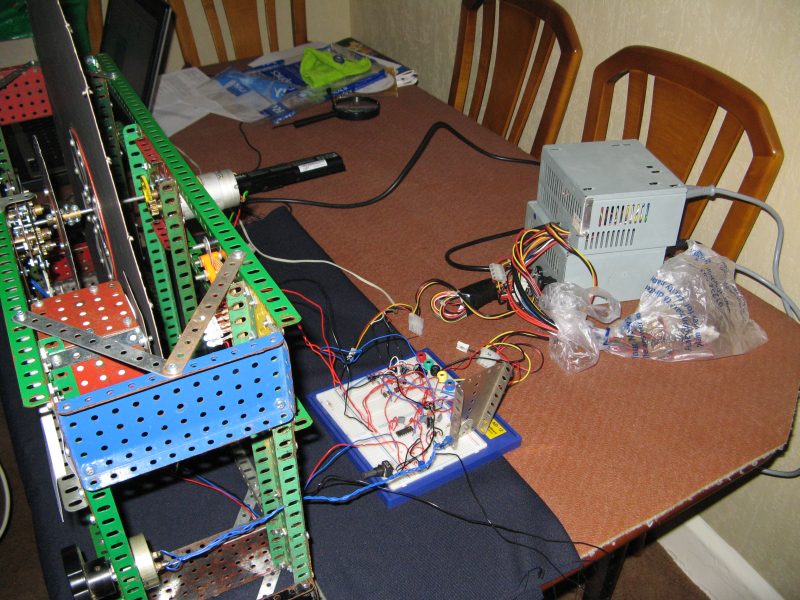
15.4 Building From Scratch: The Bill of Materials
Building a working NBTV disc televisor from nothing requires no period material, no mains wiring near the disc, and — per the NBTVA’s own documented beginner path (Vol 11, §8c; Vol 13) — a total parts cost in the tens of pounds rather than anything approaching a genuine set’s value. The club’s own construction chapter lists the complete parts list for the standard club project plainly: a wooden baseboard to build on; a pre-drilled Nipkow disc, machined on a numerically controlled cutter and sold specifically through the club’s own Club Sales operation because “the most important part of the televisor is the disc; this will determine the picture quality”; a small low-voltage DC motor (the club’s documented example recycles cassette-deck motors, also available through Club Sales); a regulated 12-volt DC power supply; the motor-drive electronics, available as a populated or unpopulated printed circuit board from the club; an LED cluster to serve as the light source; the LED-drive electronics, again available as a club PCB; and a medium-sized magnifying glass, mounted in front of the disc to enlarge the small scanned image for comfortable viewing. Every one of these items, and their real current prices, is documented in Vol 11’s account of the NBTVA’s Club Sales price list — a 12-inch disc for a few pounds, a motor for a few pounds more, PCBs at a few pounds each — putting the complete parts list for a first build within the range of a modest hobby purchase rather than a serious financial commitment.
The signal source for this first build does not need to be built at all: the club’s own recommended starting point, matching the “two honest paths” framing of this volume, is to buy one of the NBTVA’s own test-signal CDs (also available through Club Sales) and play it through an ordinary CD player’s line-out connection — not its headphone output, which the club’s own literature specifically warns degrades signal quality — directly into the sync-separator and LED-driver circuit described later in this volume. This sidesteps, for a first build, the entire question of how to generate or convert an NBTV signal in the first place, which the companion Televisor Kit Build dive on this site covers in its own dedicated detail for the specific commercial kit path; this volume’s building sequence assumes a ready-made club CD as the simplest, fastest route to an actual picture on a first build, with signal generation and conversion as a later, separate skill once the receiver itself is proven to work.
15.5 The Disc and the Motor
The disc is, per the club’s own repeated emphasis (Vol 11, Vol 13), the single component most responsible for picture quality, which is why the recommended path for a first build is to buy a pre-drilled, numerically-machined disc rather than attempt to hand-drill one — hole placement accuracy at the radial and angular pitches Vol 13 derives (11.25° steps for the club’s 32-line standard) is not realistically achievable with a hand drill and a protractor, and an inaccurately drilled disc will show its errors directly as warped or unevenly spaced picture lines no matter how good the rest of the build is. The disc mounts to the small DC motor’s shaft via a push-fit plastic coupling, itself available from the club shop, and the whole assembly is then mounted on a simple frame that lets the disc turn freely and, per the safety section above, is positioned or shielded so that no one can casually reach the spinning rim. Direct drive (motor shaft straight to disc) is the simpler option where the motor’s own bearings can support the disc’s weight; belt drive is a documented working alternative, particularly for the larger 490 mm metal disc the club’s literature describes as the natural next step once a first, smaller build is working, provided belt slippage is avoided with well-matched pulleys.
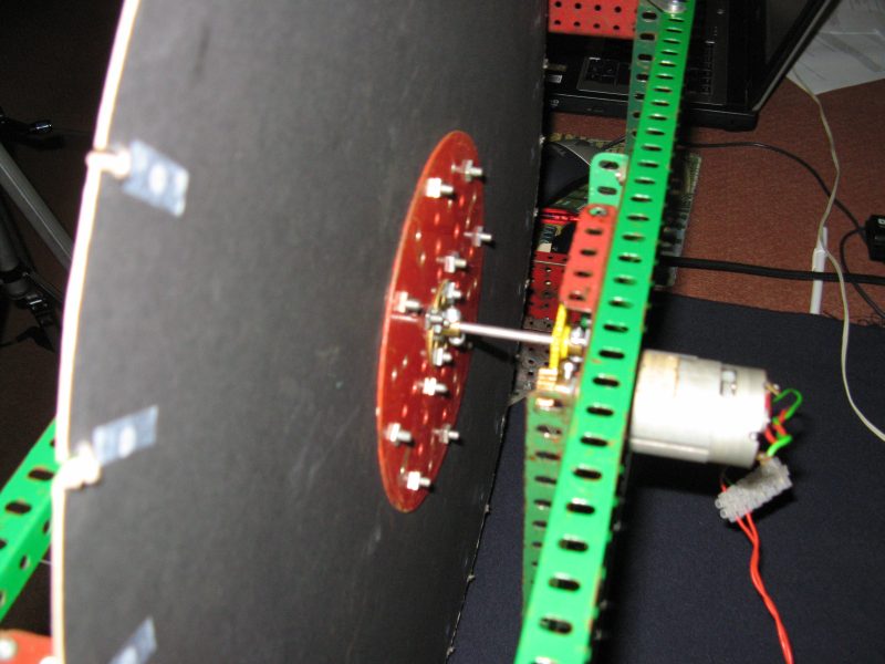
A note on scale before committing to a first build: the club’s own beginner path deliberately starts small (a 12-inch, roughly 305 mm plastic disc) precisely because it is more forgiving to build and mount than the larger 490 mm metal disc some members progress to later, which needs a correspondingly more powerful motor and a more heavily engineered mount to handle both the greater weight spinning at 750 rpm and the higher LED current needed to keep a larger scanned area adequately bright. Starting small, getting a working picture, and only then scaling up is the club’s own documented and repeatedly successful path — not a compromise made for this volume’s benefit.
15.6 The Light Source and Diffuser
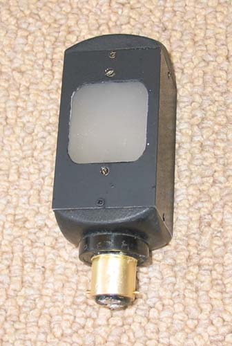
Where the historical Baird Televisor used a single flat-plate neon glow lamp — a genuinely uniform, continuously glowing surface requiring no further optical treatment, as Vol 13 explains — the modern club build substitutes a small cluster of high-brightness LEDs, and doing this well is a real, documented engineering step rather than a simple component swap. The club’s own recommendation is AlInGaP “ultra-bright” orange LEDs, chosen specifically because their colour most closely matches the historic neon glow; six devices, wired as two series chains of three (each chain dropping about 6 volts, leaving headroom on a 12-volt supply to drive the output transistor), is the club’s own documented minimum for a usable cluster. White GaN LEDs are a documented alternative for a more modern-toned display, wired in parallel banks instead of series chains because each drops a higher voltage.
The point/flat-source mismatch this creates — a handful of discrete, roughly point-like LEDs standing in for what used to be a single continuous glowing plate — is a real, documented problem the club’s own construction literature addresses directly, not a hypothetical concern: without correction, a viewer would see the individual LEDs’ positions and hot spots through the spinning disc rather than a smooth, evenly lit field. A diffuser, placed between the LED cluster and the disc, close to the spinning surface, spreads that clustered light back into something approximating the neon lamp’s original flat, even glow; the club’s own text stresses that “careful positioning of the LEDs and the diffuser is important to ensure the illumination is constant over the display area” — this is not a place to skip a step or approximate a position, both for picture quality and, per the safety section above, because the diffuser is also what keeps a bystander from looking directly into an eye-hazard-rated LED beam. A simple piece of stripboard, roughly 40 mm square, is sufficient to mount the LED cluster itself; a viewing tunnel — a light-tight enclosure around the disc and magnifying glass, echoing the original Televisor’s own viewing hood (Vol 6, §11c) — keeps ambient room light from washing out the dim picture and causing reflections off the glass surfaces.
15.7 The Sync and LED-Driver Electronics
The signal path from a bare NBTV composite video input to a modulating LED cluster runs through two purpose-built stages the NBTVA’s own literature documents in complete, buildable circuit form, both available as printed circuit boards from Club Sales. The first stage — sync separation and LED drive — takes in the composite signal (from the club CD’s line-out, or any other NBTV source), DC-restores it to a fixed reference level, extracts a clean sync pulse to feed the motor-control stage described next, and drives the LED cluster’s brightness from the remaining video content, calibrated so the video swing across the LED driver’s source resistor reads close to the standard’s own 1-volt peak-to-peak specification (Vol 12, §8d). A small deliberate non-linearity, built from extra resistor-and-diode networks in this same stage, applies the gamma correction Vol 13 explains is needed to make grey-scale reproduction from gamma-corrected broadcast-style sources look correct on an otherwise nearly-linear LED or neon display.
The second stage — the automatic speed-control circuit — is what gives a modern club build its single biggest practical advantage over the historical Baird receiver’s approach (Vol 13’s synchronization chapter covers the historical side in full and is not repeated here): rather than relying on a shared mains grid and a manual phasing knob, this circuit compares the disc’s actual rotational position, sensed optically through a ring of 32 sync holes near the disc’s rim (with one hole deliberately masked to mark the frame boundary, per Vol 12’s description of exactly this mechanism), against the sync pulses recovered from the incoming video by the first stage, and automatically corrects the motor’s drive to hold both speed and phase lock together, continuously, with no manual adjustment required once it is working. The club’s own documented tolerance for this circuit — an 8 mm opto-sensor gap, chosen specifically to “give enough clearance for a wobbly disc yet sensitive enough to cope with the small holes in the 12-inch club disc” — is a genuine, quantified engineering allowance for a real hobbyist disc that will not spin perfectly true, and is worth deliberately not over-tightening during a first build.
Both PCBs are, per the club’s own construction notes, designed the same physical length so they can be mounted side by side and interconnected with short lengths of stiff wire at the corner mounting holes for the ground planes, plus short insulated wires for the sync and +12V lines — a small detail, but one that makes a first-time build’s wiring considerably tidier and less error-prone than routing long flying leads between two separately mounted boards.
15.8 The Signal Source
A first build, as described above, needs nothing more sophisticated than an NBTVA test CD played into the sync-and-driver board’s input — and that is a deliberate, sensible simplification, not a corner cut, because it isolates “does my receiver work” from “can I generate or convert a signal,” two genuinely separate skills. Once the receiver itself is proven — a picture appears, the disc locks to speed, the framing is stable — the question of what to feed it becomes its own, larger topic: live camera sources (the NBTVA’s own camera-and-optics chapters, referenced in Vol 13, describe building a disc-based camera using the same scanning-disc principle in reverse); scan-converted standard video, using the digital scan-converters the club’s equipment chapter documents, that let an ordinary camcorder or computer act as an NBTV source; and purpose-built video-to-NBTV conversion software of the kind that turns an arbitrary video clip into an NBTV-format audio waveform for playback through a sound card. This last path — converting existing video and driving a receiver live, including from a computer or microcontroller — is exactly the territory the companion Televisor Kit Build dive on this site is built to cover in full, specific, kit-oriented detail (installing and using signal-generation software, live-streaming into a receiver, and building content specifically for the kit to display); this volume deliberately stops at “the receiver works and can display a club test CD,” and hands off the richer signal-generation question to that dive rather than duplicating it here.
15.9 Alignment and Calibration: Getting a Picture
With the mechanical assembly built and the electronics wired, per the club’s own documented commissioning sequence, calibration proceeds in a specific, checkable order rather than as a single vague “tune it until it looks right” step. First, power up without a signal applied and confirm the motor turns the disc smoothly at roughly the right speed with no signal reference yet — this isolates a purely mechanical problem (a binding bearing, a slipping coupling, a wobbling disc catching on its mount) from an electronic one before the sync circuit is even in the loop. Second, apply the NBTV signal and confirm the motor speeds up and locks — the disc’s rotational rate should visibly settle to match the incoming video’s frame rate, which for a 32-line signal shows up as a steady 400 Hz sync-pulse rate (375 Hz for a 30-line signal) measurable at the sync-separator board’s output, per the club’s own troubleshooting guidance; if this rate is absent or unstable, the fault is in signal recovery or motor drive, not yet in anything optical. Third, once speed lock is achieved, check framing — the disc’s rotational position (not its average speed) determines whether the picture assembles as a single coherent frame or appears split and torn across the middle, exactly the phase-lock distinction Vol 13 draws in detail; a build using the automatic club circuit should self-correct this continuously without a manual knob, but a build following the historical mains-synchronous approach (relevant mainly to a genuine period set, not a fresh build) would need the sort of manual phasing adjustment Vol 6 and Vol 13 describe. Fourth, focus the optics — the magnifying glass mounted in front of the disc needs its distance from the disc adjusted until the scanned lines resolve as a sharp picture rather than a soft blur, exactly the focal-length relationship Vol 13’s optics discussion sets out for a camera lens, applied here to a viewing lens instead. Fifth, set brightness and, where relevant, gamma — the LED driver’s brilliance control should be adjusted, per the club’s own instructions, until the video signal swings close to the standard’s 1-volt peak-to-peak specification across the driver’s source resistor, and a viewer using a CRT-based reference monitor to cross-check the picture should be aware of the gamma mismatch Vol 13 explains (a plain LED or neon disc televisor is very nearly linear, gamma ≈ 1, while a CRT is closer to gamma ≈ 2), which is exactly why the gamma-correction resistor network in the driver circuit exists and should not be skipped or disabled without understanding why.
None of these five checks is optional or skippable in sequence — attempting to fine-tune focus before speed lock is achieved, for instance, wastes effort adjusting an image that has not yet stopped rolling — and each one maps to a specific, previously-documented piece of engineering (Vol 12 for the signal and its sync structure, Vol 13 for the optics and synchronisation theory behind each step) rather than being an arbitrary build-day ritual.
15.10 First Light and Troubleshooting
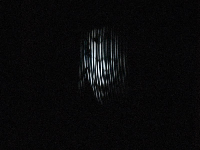
The moment a correctly built receiver first locks to a signal and resolves a recognisable picture — a face, a test card, whatever the source material happens to be — is, by every documented account this research encountered, the payoff the entire build exists to produce, and it is worth treating as a real, celebratory milestone rather than an anticlimax after so much careful bench work. It typically does not arrive as a crisp, perfect image on the first attempt; a real NBTV picture, even a correctly working one, is genuinely low-resolution, dim, and often faintly curved at the edges (the keystone distortion Vol 13 explains is a real geometric feature of scanning-disc pictures, not a fault), and expecting anything sharper than that is expecting more than the medium itself has ever delivered, in 1930 or today.
When the picture is not right, the failure modes are specific enough to diagnose rather than guess at, and Vol 13’s tolerances-and-failure-modes chapter already maps most of them; this section ties those symptoms back to the actual build steps above rather than repeating the underlying theory. No picture at all, disc not turning: check the mechanical assembly first (motor power, coupling, binding) before suspecting the electronics — this is exactly why the commissioning sequence above starts with a no-signal power-up. Disc turns but never locks to speed, or the picture rolls or scrolls vertically: this is a speed-lock failure — the disc’s average rotational rate is not matching the incoming signal’s frame rate — and points to the sync-separator or motor-drive circuit, or to the opto-sensor’s alignment and gap (the club’s own 8 mm figure, and the light-shielding note that stray light leaking around a 12-inch disc’s edge can confuse the sensor) rather than to the light source or optics. A picture appears but is split, torn, or assembled out of order: this is a phase-lock (framing) failure, distinct from speed lock, and points to the masked-sync-hole detection specifically rather than to the motor’s average speed. The picture is visible but badly blurred: check focus (the magnifying glass’s distance from the disc) before suspecting the disc’s own aperture geometry, since focus is the easier and more common culprit, and Vol 13 already explains why an oversized aperture relative to radial pitch is a separate, disc-level cause of blur that focusing cannot fix. The picture is uneven in brightness across the display, or individual bright spots are visible through the disc: this points straight back to the diffuser — either missing, too close, or poorly positioned relative to the LED cluster — rather than to the electronics, exactly the point/flat-source problem the light-source section above describes. Bright picture areas look uniformly “bleached out” with lost detail, while dark areas show plenty of gradation: this is the gamma mismatch Vol 13 explains directly — a linear LED/neon display receiving gamma-corrected broadcast-style source material — and the fix is the gamma-correction network in the LED driver, not a brightness or contrast adjustment. Working through this list in order, from mechanical to speed-lock to phase-lock to optics to light source to gamma, generally isolates a fault faster than testing everything at once — a discipline worth carrying over from the same-ordered calibration sequence in the previous section.
15.11 Cross-References
- The general theory of scanning, frame rate, and why a mechanical-television picture looks the way it does is set out in Vol 4 — Theory of Operation.
- The historical Baird Televisor’s own hardware — its disc, neon lamp, viewing hood, and manual phasing control, referenced throughout this volume’s restoration section — is dissected in full, with its confirmed hedges, in Vol 6 — Inside the Baird Televisor.
- The founding, membership, Club Sales operation, and modern build culture of the NBTVA — the source for this volume’s entire from-scratch bill of materials and build sequence — is told in full in Vol 11 — The Modern Revival: NBTV and the NBTVA.
- The NBTV signal this volume’s electronics and calibration sections assume as input — sync pulses, video amplitude, the missing line-32-to-line-1 frame sync, and the physical masked sync hole that produces it — is explained in full in Vol 12 — The NBTV Signal Explained.
- The engineering theory behind every build step in this volume — disc geometry, aperture trade-offs, light-source physics, motor choice, and synchronisation engineering — is set out in depth, and deliberately not repeated here, in Vol 13 — Optics, Discs & Mechanics in Depth.
- What can actually be acquired before any of this restoration or building begins — genuine sets, period parts, and modern club-build components, with real prices — is surveyed in full in Vol 14 — Acquiring a Mechanical Television.
- The Baird 30-line and modern NBTV 32-line standards, and the other reference figures this volume assumes, are tabulated side by side in Vol 16 — Reference and Cheatsheet.
- The companion Televisor Kit Build dive on this site picks up exactly where this volume’s signal-source section leaves off: installing and using video-to-NBTV conversion software, live-streaming into a receiver, and building the specific MindSets Online kit end to end, including its steampunk cabinet — the kit-specific companion to this volume’s general restoration-and-building guide.
Comments (0)