Mechanical TV Deep Dive · Volume 6
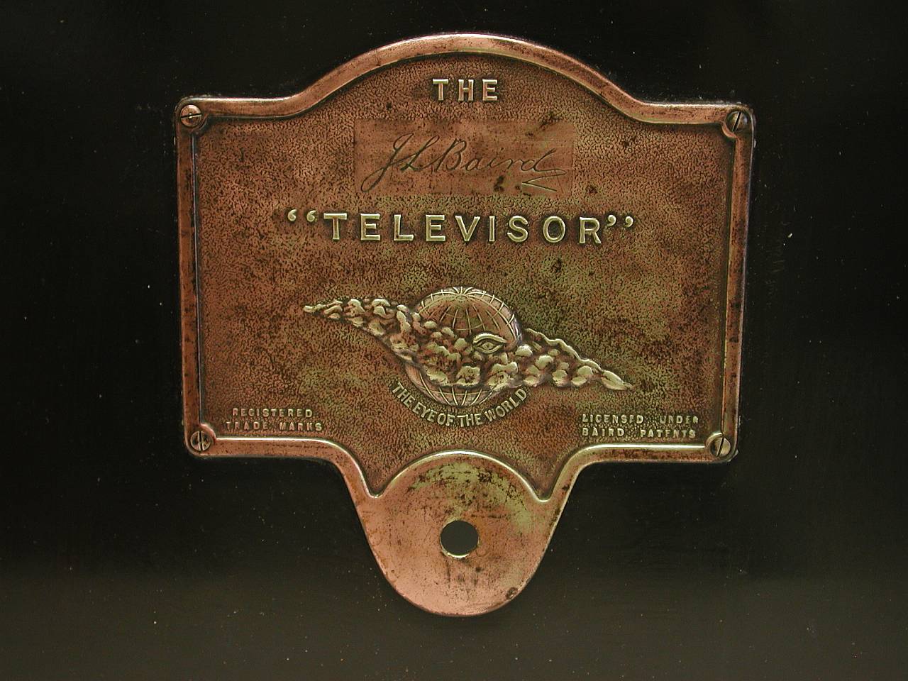
Inside the Baird Televisor
The Televisor was a domestic appliance in only the most charitable sense of the word. In form it was a cabinet roughly three feet wide and two feet high, housing a spinning disc, an electric motor, a neon lamp, and the receiving electronics necessary to extract a picture signal from a medium-wave radio broadcast. In practice it was a precision instrument that required regular attention: the viewer tuned it like a radio, adjusted its motor speed, aligned the frame phase, and peered into a viewing hood to see a postage-stamp-sized, flickering, orange image of whatever face happened to be transmitting from the BBC’s studio. That image was, nonetheless, live television — a feat that had been considered impossible a decade earlier.
This volume dissects the hardware of the Baird Televisor in detail: the disc, the motor, the synchronisation circuitry, the neon display, the cabinet, and the controls. The underlying theory of operation — why the scanning disc produces a picture, how the neon lamp modulates, why the image is orange and dim, and the mathematical basis of the synchronisation requirement — is treated in depth in Vol 4 (Theory of Operation) and is not repeated here. This volume is concerned with how those principles were realised in the specific mechanical and electrical design of the production Televisor.
6.1 The Baird 30-Line Standard
Before examining the hardware, it is useful to have the broadcast standard’s parameters precisely in view. The following table records the confirmed values from the NBTVA’s primary documentation and from corroborating technical sources. Every hardware detail in this volume — the disc’s hole count, the motor speed, the signal bandwidth — follows directly from these numbers.
Table 1 — The Baird 30-Line Standard
| Parameter | Value | Notes |
|---|---|---|
| Lines per frame | 30 | One complete rotation of the Nipkow disc produces one frame |
| Frame rate | 12.5 fps | Chosen as one-quarter of the 50 Hz UK mains frequency (50 ÷ 4 = 12.5) |
| Lines per second | 375 | 30 × 12.5; one line every ≈2.67 ms |
| Aspect ratio | 7:3 portrait (height:width) | Taller than wide; suited to close-up head shots |
| Line scan direction | Vertical, bottom to top | Each of the 30 “lines” is a vertical strip traced upward |
| Frame scan direction | Horizontal, right to left | Successive lines step from right edge to left edge of image |
| Video bandwidth | ≈10 kHz (≈13 kHz theoretical) | Fits within a medium-wave audio channel; NBTVA gives 13 kHz for truly square pixels |
| Scanning method | Progressive (no interlace) | Each aperture scans a fresh strip in sequence |
Motor speed note: at 12.5 frames per second, each complete rotation of the disc produces one frame. The disc therefore rotates at 12.5 revolutions per second, or 750 revolutions per minute (rpm). Every parameter of the synchronisation system is derived from this figure.
Aspect note: The NBTVA’s standards documentation records that in the Baird Televisor, the first three and last three of the thirty scan lines were made wider and spaced further apart than the central lines. This was a consequence of disc and motor geometry rather than a deliberate artistic choice; it altered the effective aspect ratio at the edges of the displayed image.
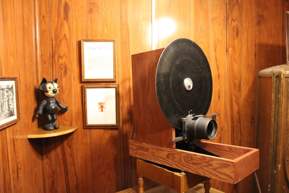
6.2 The Nipkow Disc
The centrepiece of the Televisor’s receiver was the Nipkow disc — a flat, circular disc of aluminium or other rigid material, perforated with a single-turn inward spiral of 30 apertures, one for each scan line. As the disc rotated at 12.5 revolutions per second, each aperture in turn passed before the neon display lamp, sweeping the lamp’s light across the viewing window and tracing one vertical strip of the image.
6.2.1 Disc diameter and apertures
The production Televisors used discs in the range of approximately 30–45 cm in diameter, though the exact dimensions varied between manufacturers and between factory-built and kit-built sets. (The disc dimensions were not specified in Nipkow’s 1884 patent, which described a principle rather than a construction; the 1920s–1930s implementation choices belong to the builders.) The diameter was a practical compromise: larger discs offered a wider separation between apertures and thus a cleaner image, but required a larger cabinet and a more powerful motor; smaller discs were lighter but produced a more cramped picture.
The apertures in the production Televisor were small square holes — genuine Plessey-built examples are catalogued by auction houses as “square hole” Nipkow discs (Bonhams, unit No. 192) — and were flat, not shaped lenses. Flat-aperture (plain-hole) discs were the standard approach in the Baird commercial sets. The hole diameter was chosen to balance two competing requirements: a smaller hole gives better resolution (finer vertical strips) but admits less light and thus produces a dimmer image; a larger hole is brighter but blurs adjacent strips together. The exact hole size used in production Televisors has been documented differently by different sources; early Technical Museum examples suggest holes of approximately 1–2 mm diameter at a disc radius that placed them roughly 10–13 cm from the disc’s outer edge.
Lens-aperture discs — in which small positive lenses are fitted into each hole to focus the lamp onto the viewing area, increasing light throughput — were used in some experimental and higher-quality implementations, including some NBTV designs. The production Televisor used flat holes; lens discs were the refinement pursued by later experimenters and by the hobbyist NBTV community (see Vol 13, Optics, Discs and Mechanics in Depth).
The spiral of 30 apertures was arranged so that successive holes were displaced radially inward by an equal increment. As the disc rotated, hole 1 passed the display lamp position, then hole 2 (slightly closer to the disc’s centre), then hole 3, and so on through all 30, after which the disc had completed one full rotation and the cycle began again. This arrangement converted a single complete rotation into a complete frame of 30 lines — a clean mapping that made the motor specification straightforward: disc speed = frame rate = 12.5 rev/s = 750 rpm.

6.3 The Synchronous Motor
The motor driving the Nipkow disc was a synchronous motor — a type of AC motor whose rotation speed is fixed by the frequency of its supply voltage, rather than by load conditions. In the UK, the 50 Hz mains supply governed the motor’s speed. With a correctly wound synchronous motor, the speed was locked to a precise sub-multiple of 50 Hz: 12.5 rev/s (750 rpm) corresponds to a 1:4 ratio — four mains cycles per disc revolution.
The synchronous motor’s chief virtue in this application was inherent speed stability. Once running at the correct speed, a well-made synchronous motor maintained that speed with precision, regardless of minor load changes, because any tendency to accelerate or decelerate was immediately corrected by the restoring torque from the AC magnetic field. This stood in contrast to DC motors or induction motors operating under varying load, whose speed would drift and cause the image to smear or tear.
In practice, the synchronous relationship also provided a frequency lock between every Televisor on the UK mains and the BBC’s studio, which was also mains-referenced. Both the studio’s transmitter disc and every domestic receiver disc were driven by motors governed by the same 50 Hz grid. This gave automatic speed lock at the national level: any well-designed receiver on the same grid ran at the correct speed relative to the transmitted picture, without any need for a separate speed-control signal in the broadcast. The viewer’s task was not to achieve speed lock — the mains provided that — but to achieve phase lock (framing), described in the next section.
Some early sets and kit builds used induction motors rather than fully synchronous designs; these required a separate speed-control circuit or resistor to bring the motor to approximately the right speed, after which the viewer fine-tuned it manually. The distinction between “runs at the right speed automatically” (synchronous) and “runs at approximately the right speed with adjustment” (induction or variable-speed) was not purely academic: a motor that held speed precisely made the viewing experience considerably more manageable.
The motor was typically mounted inside the cabinet below and behind the disc, connected by a direct shaft or a simple reduction drive. The disc’s hub was machined to accept the motor shaft with minimal play — any mechanical wobble in the disc plane produced visible image distortion.
6.4 Synchronisation: Speed, Framing, and Phasing
Vol 4 (Theory of Operation) established the synchronisation requirement in principle: the receiver disc must rotate at exactly the same speed as the transmitter disc and must be in exactly the same angular phase, so that each aperture at the receiver aligns with the corresponding position in the transmitted frame. This section describes how the Televisor’s specific circuits and controls achieved that requirement in practice.
6.4.1 Speed control
In sets using a synchronous motor on the UK mains, speed lock was automatic. However, the initial starting speed needed to be correct; a synchronous motor can only pull into lock at or near the synchronous speed, and must be started by other means. Production Televisors typically included a speed control — a rheostat or variable resistor — that adjusted the starting conditions of the motor until it was turning at approximately 750 rpm, at which point the synchronous pull-in action locked it to the correct speed.
Once locked, the speed control was not usually needed again during a viewing session unless the motor fell out of synchronism — which could happen if the power was interrupted momentarily or if a voltage dip caused the motor to slip poles. Re-locking required reducing the motor speed slightly with the control and allowing it to re-accelerate to the synchronous point.
6.4.2 Framing and the phasing control
Speed lock alone produced a correctly spinning disc, but not necessarily a correctly framed picture. If the disc’s phase was offset — if aperture 1 passed the lamp position when the transmitter was scanning line 8, for example — the received image was sliced and displaced: the upper portion of a face appeared at one edge of the display, the lower portion at the other. This was called an out-of-frame condition.
The phasing control corrected this. In most Televisor designs it was a small knob connected to a differential gear or a friction clutch in the disc drive — a mechanism that allowed the angular position of the disc to be shifted relative to the motor shaft by a small increment without changing the motor speed. The viewer rotated the phasing control slowly until the image snapped into its correct position, with the face centred in the display and no horizontal tearing.
Phasing required judgment. The viewer turned the control until the image appeared correctly assembled, then left it alone. If the image later began to drift or tear, the control was readjusted. In practice, once the BBC’s transmitted frame synchronisation pulse was received and the receiver circuit was responding to it, the requirement for manual phasing was reduced; but no early Televisor achieved fully automatic framing, and the viewer remained responsible for keeping the picture correctly phased throughout a viewing session.
6.4.3 The transmitted sync pulse
From the earliest days of the BBC 30-line service, a synchronisation pulse was transmitted in the brief interval between the end of one frame and the beginning of the next. This pulse — a brief electrical excursion to a level outside the normal picture signal range — served as a reference for the receiver’s framing circuitry. In well-designed sets, a sync separator stage extracted this pulse from the incoming video and used it to compare the receiver’s phase against the transmitted phase, producing an error signal that drove a correction to the disc position.
The practical effectiveness of this sync extraction depended on signal strength and the quality of the sync circuit. In marginal reception conditions, the sync pulse was buried in noise and the circuit offered little assistance; the viewer fell back on manual phasing. In strong-signal conditions, a good sync circuit could hold the frame position stable for extended periods without manual intervention. The quality of a Televisor’s sync circuit was accordingly one of the clearest differentiators between a well-designed commercial set and a bare-bones kit build.
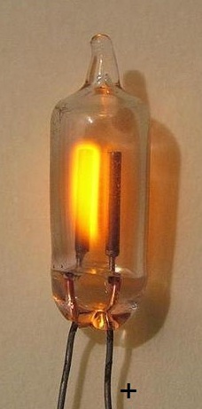
6.5 The Neon Glow-Lamp and Optical Display
The image source in the Televisor was a flat-plate neon glow-discharge lamp — a sealed glass enclosure containing neon gas at low pressure, with two flat parallel electrodes producing a uniform rectangular glow discharge. Vol 4 explained why neon was chosen (response speed in the microsecond range, far faster than any incandescent alternative) and why the image was orange (the dominant emission lines of neon gas fall in the orange-red range, 585–640 nm). This section describes the optical arrangement that converted the lamp’s discharge into a displayed image.
6.5.1 The flat-plate lamp
The lamp’s active area — the glowing discharge between the electrodes — was sized to match the image window. Surviving museum specimens and enthusiast reconstructions (no Baird Television Ltd engineering drawing of the lamp is known to survive) suggest an active area on the order of 25–35 mm wide and 55–75 mm tall, in the portrait 7:3 proportions of the image. The flat-plate construction produced a uniform glow over this area, so that every aperture in the sweeping disc sampled approximately the same total brightness from the lamp; the modulation of that brightness by the incoming video signal was what created the picture.
The lamp was driven from the video amplifier through a resistor that set the operating point: a standing bias voltage maintained the neon discharge at a threshold just above extinction, so that even the darkest parts of the picture kept the discharge alive (extinguishing and re-striking a neon discharge was too slow for reliable operation at 10 kHz video bandwidth). The video signal then varied the discharge current — and hence its brightness — above and below this operating point.
6.5.2 Lenses and the viewing aperture
The image formed by the sweeping disc apertures was small — the image window matched the face of the flat-plate lamp, on the order of 30 mm × 70 mm by these same reconstructed figures (no original specification survives). To make the image viewable, a condenser lens or magnifying glass was positioned between the disc and the viewer’s eye, focusing the image and enlarging it slightly. Even with magnification, the resulting picture remained comparable in area to a large postage stamp; the purpose of the lens was primarily to concentrate the available light onto the viewer’s pupil rather than to dramatically enlarge the image.
Some implementations positioned the magnifying lens as an integral part of the viewing hood; others mounted it on the cabinet face in a fixed tube.
6.5.3 The viewing hood
Because the neon lamp’s useful light output, divided among 30 apertures each sweeping for 1/30 of a frame, produced a very dim displayed image, all production Televisors included a viewing hood — a light-tight enclosure attached to the front of the cabinet that surrounded the display window and excluded ambient light. The viewer pressed their face into the hood, allowing the eye to dark-adapt to the lamp’s output. In a darkened room with the eye fully adapted, the image was adequately visible; in a normally lit room with the hood removed, it was essentially invisible.
The hood was typically a flanged box of cardboard, wood, or moulded material, approximately 10–15 cm deep, lined with dark fabric or paint. It was not an elegant feature — it imposed an intimate and rather awkward posture on the viewer — but it was engineering necessity. A brighter lamp would have allowed a less restrictive design, but would also have created excessive heat and placed demands on the neon driver circuit that exceeded 1930s component capabilities.
6.6 The Cabinet, Controls, and Physical Layout
The production Televisor was supplied in a wooden cabinet, typically measuring approximately three feet (roughly 90 cm) wide by two feet (60 cm) high. This was significantly larger than a radio set of the period, the extra space being required to accommodate the Nipkow disc and its motor. The disc occupied a large central space inside the cabinet, with the motor behind it and the electronics — valve amplifiers, power supply, detector, and neon driver — arranged in the remaining space, typically to one side or below the disc.
6.6.1 The front panel
The front panel of the Televisor presented the viewer with the viewing hood aperture — the opening into which they looked to see the picture — and a row of controls. Production Televisors typically provided at minimum:
- A tuning control, for selecting the broadcast frequency (MW radio tuning).
- A speed control, for adjusting and locking the motor to 750 rpm / 12.5 rps.
- A phasing (framing) control, for aligning the disc’s phase to the transmitted frame.
- A brightness control, adjusting the bias and modulation depth of the neon lamp.
Some models also provided a volume control and a loudspeaker for the audio component of the broadcast; the BBC’s 30-line service transmitted sound and vision, initially on separate frequencies (requiring the viewer to retune between them) and from March 1930 on a combined transmission.
The controls were not arranged for casual operation. Adjustment of the speed and phasing controls required a degree of skill and patience: the viewer turned the speed control until the image stopped rolling, then adjusted the phasing control until the image snapped into a correctly positioned frame, then re-checked the speed. This sequence — tune, lock speed, frame the picture, adjust brightness — was the routine start-up procedure for a 30-line viewing session.
6.6.2 Manufacture and pricing
The Televisor was manufactured principally by Plessey in England from approximately 1929, with commercial availability to the public from 1930. Approximately 1,000 units were produced over the course of the 30-line service’s run (1930–1935). The price varied by source and sales period: figures of approximately £18 and approximately £26 (around 25 guineas) both appear in the historical record, with the higher figure more commonly cited in museum and auction house documentation. The discrepancy likely reflects different models, different periods, or different market channels. At either price, the Televisor was a significant purchase — the equivalent of several weeks’ wages for a typical working-family income of the period.
The set was also available in kit form. DIY kits, sold through Baird Television Ltd and through enthusiast suppliers, provided the mechanical and electronic components for assembly by the buyer. Kit sets were reportedly cheaper than factory-built Televisors and, among the technically inclined, appear to have outsold the production set. Buyers of either form signed a contract specifying the available programming — an arrangement that underlined the set’s novelty: it was sold not just as a device but as access to a broadcast service.
6.7 The Receiver Signal Path
The electronic signal processing in the Televisor followed a straightforward chain: aerial reception, radio-frequency amplification and detection, audio separation, and video amplification to drive the neon lamp. The diagram below maps the complete signal path.

The valve count in a production Televisor was modest by the standards of contemporary radio sets — typically three to five triode or pentode valves, depending on whether audio amplification was included (the exact count is reconstructed from kit and museum documentation rather than a factory specification). The power supply drew from the mains and provided the high-tension voltages required by the valves and the neon lamp bias.
The absence of any carrier in the TV signal path that needed to be recovered separately — the BBC transmitted the video signal as an audio-frequency signal, directly amplitude-modulating a standard medium-wave carrier — meant that an existing radio receiver could, in principle, supply the detected video directly to a Televisor display section. Several commercial adaptor kits exploited this, allowing the owner of a broadcast radio set to add only the mechanical display section (disc, motor, neon lamp, and minimal amplification).
6.8 Original Schematics and Engineering Drawings
The Baird Televisor was not a widely documented design in the manner of post-war mass-produced electronics. Surviving original circuit diagrams and engineering drawings are scarce, and those that exist are distributed across several archives.
6.8.1 Science Museum Group Collection
The Science Museum Group Collection holds several items of early Baird television apparatus, including transmitter and receiver components from the 1925–1930 period. The collection catalogue (accessible at collection.sciencemuseumgroup.org.uk) lists specific objects with accession numbers; some include engineering drawings or photographic documentation of internal construction. This is the single most authoritative institutional source for physical evidence of early Televisor construction.
6.8.2 NBTVA Archives
The Narrow-Bandwidth Television Association (NBTVA) maintains a technical archive relating to both original Baird designs and the subsequent NBTV hobbyist standard. The association’s website (http://www.nbtv.wyenet.co.uk/) includes circuit documentation and references to period publications; the NBTVA’s newsletter and proceedings contain reprinted schematic diagrams from primary sources. The association is also the best point of contact for researchers seeking scans of period circuit diagrams from Baird’s own technical staff.
6.8.3 Period publications
Original Televisor circuit diagrams appeared in contemporary electronics publications — notably in the Baird Television Development Company’s own technical bulletins and in the periodical press of the early 1930s (including the Wireless World and its contemporaries). These have been partially digitised and reproduced in enthusiast and museum contexts; the cool386.com clone-building project provides a detailed reconstruction of a period-consistent 30-line receiver circuit, based on primary and secondary sources, and may serve as a practical reference for those unable to access original documentation directly.
6.9 The Viewing Experience
A detailed account of the 30-line viewing experience — the social context, the BBC programming, and how audiences responded — appears in Vol 8 (The 30-Line Broadcast Era). The mechanical reality of watching the Televisor was as follows.
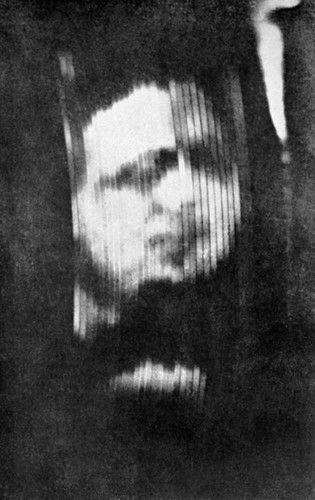
The viewer placed their face into the viewing hood, which excluded most of the room’s ambient light. In front of their eye, through a lens, the Nipkow disc was spinning — invisible at speed, perceived only as a slight disturbance in the air. The orange glow of the neon lamp, modulated by the incoming signal and filtered by the sweeping disc apertures, produced a small rectangular image roughly 30 mm wide and 70 mm tall, in portrait orientation.
The image showed a single face — a presenter, a performer, or a demonstration subject — in close-up. The resolution was approximately 30 vertical strips by 50 brightness samples per strip: enough to make the eyes, nose, and mouth of a face legible, and to convey gross movements of the head, but not enough to read an expression clearly or to distinguish a complex background. The frame rate of 12.5 per second produced a slightly flickering image; the orange emission of the neon was visible in peripheral vision as an amber glow.
Before that picture appeared, the viewer had:
- Tuned the set’s radio stage to the BBC’s medium-wave television frequency (on a separate wavelength from the sound, before March 1930; combined thereafter).
- Started the disc motor and adjusted the speed control until the motor pulled into synchronism at 750 rpm.
- Adjusted the phasing control until the image snapped into a correctly framed position — usually identifiable by the face appearing whole rather than split horizontally across the display.
- Adjusted the brightness control to optimise the visible contrast.
The full procedure took several minutes for an experienced operator; longer for a first-time viewer. It was emphatically not a “switch it on and watch” experience. The Televisor demanded engagement and adjustment, and rewarded only those who had either read the manual carefully or had someone to show them the sequence.
The picture, once established, required occasional re-phasing as warmup caused the motor to settle and as the mains frequency underwent minor variations. The viewer remained actively engaged with the set throughout the session — one hand near the phasing control, eye pressed to the hood, monitoring the image for drift.
This was the reality of the world’s first commercial television service. The BBC broadcast for thirty minutes to an hour most evenings, after the main radio programme; viewers who had their sets correctly adjusted saw a face, in orange, roughly the size of a stamp, hovering in the dark of the viewing hood. It was enough to be extraordinary.
6.10 Cross-References
- The mathematical basis of the scan geometry, bandwidth, and flicker behaviour: Vol 4 — Theory of Operation.
- The biography of John Logie Baird and the demonstrations that preceded the commercial Televisor: Vol 5 — John Logie Baird & the First Television.
- The BBC broadcast service that the Televisor was designed to receive: Vol 8 — The 30-Line Broadcast Era.
- Engineering detail on disc design, lens apertures, and motor synchronisation methods: Vol 13 — Optics, Discs and Mechanics in Depth.
- What a genuine Televisor is worth today, and what actually comes to market: Vol 14 — Acquiring a Mechanical Television.
Comments (0)