Mechanical TV Deep Dive · Volume 3
Nipkow's Disc (1884)
Paul Nipkow’s 1884 patent never produced a working machine. It did something rarer: it produced an idea so complete and so exactly right that inventors forty years later built their first television sets around it without changing a single principle. The scanning disc at the heart of every Baird Televisor, every Jenkins Radiovisor, every hobbyist NBTV receiver built in the last century is, in its essentials, the device Nipkow described in six pages of patent text on a January evening in Berlin.
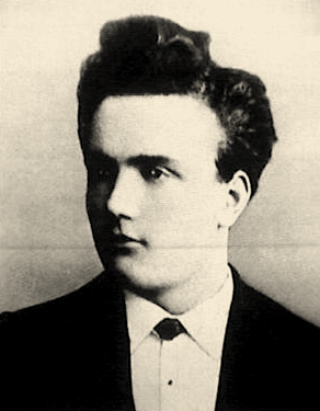
3.1 Paul Nipkow — The Inventor
Paul Julius Gottlieb Nipkow was born on 22 August 1860 in Lauenburg in Pomerania (present-day Lębork, Poland). He moved to Berlin to study physics and engineering and became, by his mid-twenties, an unremarkable student with an extraordinary preoccupation: the transmission of a complete, moving image over a wire.
The idea came to him, by his own later account, on Christmas Eve of 1883. He was sitting alone in his rented room at Philippstraße 13a in Berlin — a student too poor to travel home for the holiday — and found himself thinking about how to see his distant family in Lauenburg. From that longing, he conceived what he called a “telephone for pictures”: a means of transmitting a visual image over a wire. He had been wrestling with what seemed to be the fundamental impossibility of sending a two-dimensional picture through a one-dimensional electrical conductor — a single wire or channel can carry only one value at a time. The solution he conceived was not to send the whole image at once but to send it serially: to break the image into a sequence of brightness values, transmit each value in turn, and rely on the persistence of the human eye to reassemble them into a picture.
The mechanism he imagined for doing this was elegant in its simplicity. A flat disc, perforated with a series of small holes arranged in a precise inward spiral, would be spun in front of the image to be transmitted. As the disc rotated, each hole would sweep across the image in a narrow strip — one line — before the next hole, set slightly closer to the center, swept the next strip below it. One complete revolution of the disc would decompose the entire image into a sequence of brightness values, each value corresponding to a tiny area of the original scene.
On 6 January 1884, six weeks after his Christmas Eve inspiration, Nipkow filed his patent with the Imperial German Patent Office. He was twenty-three years old, and he could not afford the filing fee. His girlfriend, Sophia Colonius, paid it for him.
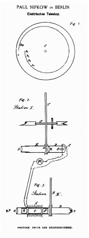
3.2 The Patent: Elektrisches Teleskop (DE 30105)
The Imperial German Patent Office granted Nipkow’s patent on 15 January 1885 under the number DE 30105 and the title Elektrisches Teleskop — “Electric Telescope.” The term “television” did not yet exist; Nipkow and his contemporaries framed the problem as one of seeing at a distance, in analogy to the telescope.
The patent claimed a complete system for transmitting and receiving images electrically. At the transmitting end, a disc perforated with a one-turn spiral of apertures rotated in front of the scene to be transmitted, driven by clockwork. Behind the disc, facing the scene, a selenium photocell converted the varying brightness of the light passing through each aperture into a corresponding variation in electrical current. This varying current was transmitted to the receiving end. There, a second disc — identical to the transmitter disc and synchronised to rotate at the same speed — rotated in front of a light source that varied its brightness in response to the incoming electrical signal. An observer looking through the apertures of the receiver disc as they swept past would, persistence of vision combining the successive spots of light, perceive a reproduced image of the scene.
The patent thus captured, in one document, every essential element of mechanical television:
- image decomposition by sequential scanning (the transmitter disc);
- opto-electrical conversion (the selenium photocell);
- electrical transmission of the resulting signal;
- electrical-to-light reconversion at the receiver;
- image reconstruction by scanning in synchrony (the receiver disc);
- and the role of the viewer’s visual persistence in integrating the scanned image into a perceived whole.
3.3 How the Disc Decomposes a 2-D Image
The core insight of the Nipkow disc is the conversion of a two-dimensional spatial pattern (the image) into a one-dimensional temporal signal (the varying electrical current) and back again. The mechanism depends on three properties acting in concert: rotation, a spiral of apertures, and synchronisation.
3.3.1 The Scanning Sequence
Consider a disc with N small holes drilled through it, arranged in a single inward turn of a spiral. The disc is placed between the scene and the photocell, so that only the light passing through the holes reaches the photocell. As the disc rotates at a constant angular speed:
-
Hole 1 — the outermost aperture — passes across the image area first. Because it is the outermost hole, it sweeps across the uppermost strip of the image (the first line). As it crosses the bright and dark regions of that strip, the amount of light reaching the photocell varies accordingly. The photocell converts these variations into a varying electrical current: bright areas produce high current, dark areas low current.
-
As the disc continues to rotate, hole 1 moves on past the image area. The image area goes momentarily dark (between holes, no aperture is in front of it). Then hole 2, positioned slightly closer to the centre of the disc, arrives at the image area. It sweeps across the second strip of the image — one step lower than the first — producing a second sequence of brightness values as an electrical signal.
-
This continues for all N holes. When hole N, the innermost aperture, has completed its sweep of the Nth (lowest) strip, the disc has completed exactly one full revolution, and one complete frame of the image has been transmitted.
At the receiving end, a second disc — physically identical and turning at exactly the same speed and in the same phase — rotates in front of a modulated light source. Each hole in the receiver disc, passing before the lamp at the same angular position as its counterpart in the transmitter, illuminates the corresponding point in a reconstructed image. An observer’s eye integrates the N successive strips into a single picture.
3.3.2 From 2-D to 1-D and Back
The transformation the disc performs can be thought of precisely: the two spatial coordinates of the image (horizontal position within a line, and vertical position from line to line) are mapped onto a single time axis.
Within a single sweep of one hole across the image area, the horizontal position of the illuminated point changes with time — it traces from one side of the image to the other as the disc rotates. The rate of this sweep determines the horizontal resolution available: faster rotation (or a wider image aperture) gives less time per horizontal unit, reducing horizontal resolution; slower rotation gives more time per unit, improving it.
Between successive holes, the vertical position steps downward by one line. The number of holes N thus sets the vertical resolution directly: N holes yield N lines of vertical resolution per frame.
The rate at which the disc rotates determines the frame rate: if the disc makes F complete revolutions per second, the system produces F frames per second. The human eye requires approximately 10–16 frames per second to fuse successive images into the illusion of smooth motion (and more to eliminate obvious flicker). These constraints on frame rate, hole count, and image quality are linked through bandwidth — a topic developed more fully in the next volume.
3.4 The Geometry of the Spiral
The precision of the aperture layout determines the quality of the image. Nipkow’s patent established the principles; later builders worked out the engineering geometry in detail.

3.4.1 Angular Spacing
For a disc with N holes and a one-turn (360°) spiral, the angular separation between adjacent holes is 360°/N. This spacing ensures that when hole k has completed its sweep of line k and exited the image area, hole k+1 arrives at the image area at exactly the start of the next line. No two holes are simultaneously in front of the image area (provided the image area subtends less than 360°/N of arc), which prevents one line from overlapping another.
3.4.2 Radial Spacing (Spiral Pitch)
Each successive hole is positioned at a slightly smaller radius than the previous one. If r₁ is the radius of hole 1 (the outermost) and rN is the radius of hole N (the innermost), the radial pitch p — the step inward from one hole to the next — is:
p = (r₁ − rN) / (N − 1)
The pitch p sets the height of each scan line at the image plane: the aperture sweeps a strip of height approximately equal to p. For the lines to meet without gap or overlap, the image window’s total radial extent should equal r₁ − rN, spanning from the outermost to the innermost hole position.
3.4.3 Aperture Size and Resolution
Each hole is a small circular or rectangular opening. The size of the aperture sets a lower bound on the spot size at the image plane — a larger hole illuminates a broader strip per pass, reducing vertical and horizontal resolution. For a given disc size and line count, the aperture diameter must be small enough that each hole samples only one line’s worth of vertical image height, yet large enough to admit useful amounts of light.
As the hole count N increases (finer vertical resolution), the pitch p must decrease for a disc of given size, and the holes must be made smaller. This is a practical constraint: very small holes admit very little light, requiring either a brighter illumination source or a more sensitive photocell. In Nipkow’s era, neither was available at adequate levels.
3.4.4 Disc Diameter and Image Size
The image projected through the aperture window occupies an area roughly p (height) × arc swept during one hole transit (width). For a disc of radius r and an image window subtending angle α (in radians), the image width is approximately r × α. A larger disc permits either a larger image or finer apertures for the same image size — practical disc diameters in later working systems ranged from a few centimetres in tabletop hobbyist sets to tens of centimetres in high-line-count experimental systems.
3.5 The Photocell and Signal Chain
At the transmitting end, Nipkow’s patent specified a selenium photocell as the light-to-electricity converter. The use of selenium followed directly from Willoughby Smith’s 1873 discovery that selenium’s electrical resistance varies with the intensity of light falling on it (described in Vol 2 of this series). A selenium rod or thin film placed behind the disc aperture would produce a varying current as each hole swept bright and dark areas of the image.
At the receiving end, the varying signal current controlled a light source — Nipkow’s patent described a lamp whose brightness varied in step with the incoming current. An observer looking through the receiver disc, with the disc spinning in synchrony with the transmitter, would see a reconstructed image built up line by line as each hole swept its corresponding zone of the display.
The two discs had to rotate at identical speed and in identical phase — a requirement Nipkow acknowledged but did not solve. Synchronisation of two mechanical systems at a distance, without a common driving shaft, was an unsolved engineering problem in 1884. His patent specified clockwork-driven discs but offered no mechanism for keeping them locked to each other.
3.6 Why It Was Never Built
Nipkow’s patent lapsed after a few years; he could not afford the renewal fees, and the device existed only on paper. The German Patent and Trade Mark Office (DPMA) records explicitly that “it is assumed that Nipkow never attempted to realise or test his ‘electric telescope’ in practice.” Three technical obstacles made working realisation impossible with the technology of 1884:
Selenium lag. Selenium cells respond slowly to changes in light — far too slowly for the rapid brightness variations of a scanned image. A disc rotating fast enough to produce even crude motion (ten or more frames per second) sweeps each aperture across its image strip in a fraction of a millisecond. A selenium cell’s response time in 1884 was orders of magnitude too slow to follow such rapid changes; the output would have been a blurred smear rather than a resolved image. This was the decisive technical barrier.
No amplification. The tiny current from a selenium cell illuminated by a small aperture scanning a dimly lit scene is extremely small. In 1884, there was no means of amplifying it to drive a useful light source at the receiver. The electron valve (vacuum tube) that would make amplification possible was not demonstrated until the early twentieth century; the transistor lay decades further. Without amplification, the signal-to-noise ratio was hopeless.
Synchronisation. Keeping two mechanically independent discs in exact phase synchrony at transmitter and receiver — over a distance of any significance — was not solvable with clockwork. Even a tiny speed difference would cause the received image to roll or tear. Practical synchronisation required either a shared electrical reference signal or purpose-built synchronous motor control; neither existed in 1884.
Practical isolation. Beyond these technical barriers, Nipkow was a student with no laboratory, no funding, and no institutional backing. He filed the patent as a theoretical claim and moved on to a career in electrical engineering that had little further to do with image transmission.
3.7 Rediscovery and Belated Recognition
Nipkow’s patent lapsed into obscurity. For decades it sat unread in the patent archives while inventors interested in distant image transmission pursued other approaches — notably the use of selenium mosaic arrays (the “telectroscope” proposals of Carey and others) or the photoelectric facsimile machines that transmitted still images over telegraph lines.
The revival of the scanning-disc principle happened in two waves. The first was technical: from around 1922, a new generation of engineers — armed with thermionic amplifiers, neon lamps capable of rapid modulation, and synchronous electric motors — independently discovered that a spinning perforated disc could now scan an image fast enough to produce recognisable moving pictures. By 1925–1926, John Logie Baird in Britain and Charles Francis Jenkins in the United States had both produced working Nipkow-disc demonstrations; on 25 December 1926, Kenjiro Takayanagi in Japan demonstrated a 40-line hybrid system using a Nipkow disc at the transmitter and a cathode-ray tube at the receiver — the first use of a CRT for television display. In Germany, Dénes von Mihály worked with the Nipkow disc but his confirmed public demonstrations came later: a first cable transmission in early 1928 and a public showing at the Berlin Funkausstellung in August 1928. Max Dieckmann’s 1925 German work, carried out with Rudolf Hell, was a different matter entirely — an electronic image-dissector using a Braun tube (CRT), not a Nipkow-disc mechanical system. Baird never publicly credited Nipkow in any surviving record; none of the others formally cited the expired patent either, having each arrived at its principle independently without reference to the 1884 document lying unread in the archives.
The second wave — the public recognition of Nipkow himself — came in 1928. At the fifth Große Deutsche Funkausstellung (Great German Radio Exhibition) in Berlin, opening 31 August 1928, working television demonstrations drew large crowds and prompted the German press to ask who had first conceived the scanning-disc idea. German journalists — among them Heinz Dillge and Eduard Rhein — identified DE 30105, and Nipkow found himself, 45 years after his Christmas Eve inspiration, suddenly famous as the originator of television.
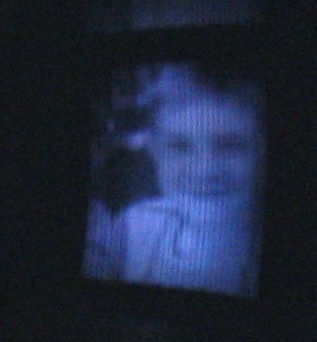
Nipkow went to the exhibition and saw working television for the first time. He joined the queues of spectators waiting to enter the darkened viewing booths, and when he finally reached the front, a cloth was drawn aside to reveal a flickering image. By his own account, he was not overwhelmed: the picture was not yet what he had in mind. But the recognition was now permanent. German newspapers widely called him the “Vater des Fernsehens” — the Father of Television — and the title stuck.
In 1935, on the occasion of his 75th birthday, Nipkow received an honorary doctorate from Goethe-University Frankfurt. That same year, the world’s first regular public television station — opened in Berlin on 22 March 1935 — was named the Fernsehsender “Paul Nipkow” in his honour. The Nazi regime, eager to claim television as a German invention, gave Nipkow the title of honorary president of the television council of the Reichsrundfunkkammer. In 1936, the Berlin Olympic Games — the first televised Olympics — were broadcast on the station bearing his name. In 1937, he appeared on television himself.
Nipkow died on 24 August 1940, two days after his eightieth birthday. His state funeral was broadcast live on television — reportedly the first such honour for a German engineer. He had witnessed not only the realisation of the idea he had conceived on a lonely Christmas Eve in 1883 but also its supersession, within his own lifetime, by all-electronic television systems that owed him a debt he never formally collected.
The scanning disc has since carried his name. In every language and every technical tradition, the device is the Nipkow disc — a rare case of eponymous precision, given that Nipkow both conceived the device and described its operating principle completely, forty years before anyone made it work.
3.8 What the Patent Did Not Cover
A reading of DE 30105 shows what Nipkow described in full and what he left unspecified. He described the principle: a one-turn spiral of apertures, one hole per scan line, synchronous rotation at transmitter and receiver, and a selenium photocell converting brightness to current. He did not specify — and could not usefully specify — the disc diameter, hole size, or radial pitch of the spiral. Those construction details depended on the performance of components that did not yet exist in useful forms. The patent body labels the apertures generically as “D₁ D₂ D₃ …” with an ellipsis and does not state a count; only the patent’s worked example drawing shows 24 holes (yielding a 24-line image), as an illustration of the principle rather than a requirement. The two concrete numbers in the patent are operational rather than dimensional: a rotation rate of one-tenth of a second per revolution (10 frames per second, matching persistence of vision) and a 0.5 mm axis shift that belongs to an alternative claim for a copy-telegraph mechanism. Every “30 cm disc, 30 holes” or “48 cm disc, 48 holes” figure one encounters in the historical record comes from 1920s and 1930s builders — not from Nipkow.
This breadth proved its durability. When the 1920s inventors built their systems with different line counts (Jenkins used 48 lines; Baird used 30; later German systems used 60 or more), different disc sizes, and different motor arrangements, they were all still operating within the framework of DE 30105. The patent, had it remained in force, would have covered them all. As it was, it had lapsed, and the inventors of the 1920s were free to build on Nipkow’s idea without licence or payment.
3.9 Connections to the Rest of the Series
The next volume (Theory of Operation) extends the analysis begun here, working through the mathematics of frame rate, flicker, bandwidth, and why the resulting signal fits within an audio channel. The inside of the Baird Televisor — the most successful commercial embodiment of Nipkow’s disc — is examined in Vol 6 (Inside the Baird Televisor), with the 30-line standard’s specific geometry traced there. Vol 13 (Optics, Discs & Mechanics in Depth) covers disc manufacture, aperture design, and the tolerances required for a sharp, stable picture. The modern hobbyist continuation of the scanning-disc tradition is taken up in Vol 11 (The Modern Revival: NBTV & the NBTVA).
Comments (0)