Mechanical TV Deep Dive · Volume 4
Theory of Operation
Every mechanical television system reduces to a single act performed thirty times a second: converting a two-dimensional image into a one-dimensional electrical signal, transmitting that signal through a channel, and converting it back into an image. The Nipkow disc, as Volume 3 established, provides the mechanical means of decomposition and reconstruction. This volume traces what happens to the signal between those two endpoints — the mathematics that govern scanning rate, the geometry that determines what the image looks like, the physics that explains why the picture is orange and dim, and the engineering that keeps two spinning discs, separated by distance, locked in step with each other.

4.1 The Mathematics of Scanning
The Baird 30-line system, as established by the BBC broadcast standard and confirmed against the Narrow-Bandwidth Television Association’s primary documentation, operates with three interlinked numbers: 30 lines per frame, 12.5 frames per second, and the product of those two — 375 lines per second. Every other parameter of the signal is derived from, or constrained by, these three.
The frame rate of 12.5 frames per second was not arbitrary. The UK mains supply frequency of 50 Hz is exactly four times 12.5: one full revolution of the scanning disc every 80 milliseconds spans four complete mains cycles (a 1:4 disc-to-mains frequency ratio). This relationship made synchronisation tractable. A synchronous motor driven from the local mains supply would run at a sub-multiple of mains frequency, and since the BBC’s studio equipment and every domestic receiver were both connected to the same national grid, both disc drives shared the same underlying frequency reference. The choice of 12.5 fps was thus an engineering convenience as much as a perceptual one.
At 375 lines per second, each line — each complete sweep of one disc aperture across the image area — lasts 1/375 of a second, or approximately 2.67 milliseconds. Within this 2.67 ms window, the signal must encode every brightness variation along the full length of that scan line. The input constraint is the medium-wave audio channel available for broadcasting: the BBC’s medium-wave transmitters of this era could carry audio — and hence video — to approximately 10 kHz. From this ceiling, the maximum number of distinguishable brightness transitions per line follows directly: a 10 kHz channel can encode at most 2 × 10,000 × 0.00267 ≈ 53 transitions in 2.67 ms. The image thus contains roughly 30 columns and 53 rows of picture elements (as the Scan Geometry section explains, each “line” is a vertical strip, so the 30 lines form 30 columns and the brightness samples along each strip form the rows) — approximately 1,600 in total. A modern high-definition frame contains roughly two million. The NBTVA’s own analysis gives approximately 13 kHz as the theoretical bandwidth required for square picture elements given the 7:3 portrait aspect ratio; in practice, the medium-wave audio channel accommodated approximately 10 kHz, giving picture elements that are slightly taller than wide.
4.2 The Scan Geometry: Vertical Lines, Horizontal Frame
The terminology of mechanical television is a persistent source of confusion because the word “line” carries a different meaning than it does in modern television. In the Baird 30-line system and in the NBTV standard that descends from it, each of the 30 scan “lines” is not a horizontal row — it is a vertical strip.
The scanning disc apertures sweep the image from bottom to top. As one aperture crosses the image window, it traces a path from the bottom of the image area to the top, sampling brightness values along the way. That vertical sweep constitutes one “line” in the Baird system. The disc then advances to the next aperture, which is set slightly closer to the disc’s centre and thus sits one strip further to the left in the image window. This successive stepping from right to left as the disc rotates constitutes the frame scan direction.

To state the geometry precisely, in accordance with the NBTVA’s primary documentation:
- Line scan direction: vertical, bottom to top. Each aperture sweeps upward across the image.
- Frame scan direction: horizontal, right to left. Successive apertures step the image position progressively leftward.
- Aspect ratio: 7:3 in height-to-width terms (portrait). The image is taller than it is wide. Expressed as a width-to-height ratio, this is 3:7. A modern widescreen television has an aspect ratio of 16:9; the Baird image, by comparison, is a narrow upright rectangle barely wider than a finger.
The NBTVA’s documentation notes one further detail of the Baird standard: the first three and last three lines of each frame were made wider and spaced further apart than the central lines. This altered the effective aspect ratio at the edges of the image and was a consequence of the practical geometry of the disc and its motor drive rather than a deliberate design feature.
The portrait format was not an accident. It suited the only subject the system could realistically display: a human face at close range. At 30 vertical strips and approximately 53 brightness samples per strip, a full body would be unrecognisable; a face, filling the narrow upright rectangle, was at the edge of legibility. The frame shape was tailored to the content it could plausibly transmit.
4.3 Flicker and Persistence of Vision
At 12.5 frames per second, the Baird image flickered. Flicker is perceptible whenever the eye detects a distinct on-off cycle in the image, and the threshold at which flicker becomes invisible — the critical flicker fusion frequency — is not a fixed number but depends on the luminance of the source. For a bright display observed in a dark room, fusion may require 50 Hz or more; for the dim, orange glow of a neon lamp, it can fall as low as 15–20 Hz. The Baird system, with its inherently dim image, exploited this relationship: the very dimness of the picture that made it frustrating to view also reduced the perceived severity of flicker. A viewer peering into the Televisor’s viewing hood in a darkened room would find the flicker manageable in a way that a brighter 12.5-fps display would not be.
Persistence of vision — the retinal after-image that allows a brief stimulus to persist for approximately 50–100 ms — provides a second mitigation. At 12.5 fps, each frame lasts 80 ms, which falls within the range of useful visual persistence. The eye effectively integrates the scan lines within a frame into a single image rather than perceiving 30 separate strips in succession. The disc spins so fast that individual aperture sweeps are invisible; the viewer sees not a moving spot but a complete, if dim and slightly flickering, picture.
Television engineers of the 1930s accepted 12.5 fps as a deliberate compromise: enough frames per second for persistence of vision to fuse them into the illusion of motion, yet few enough that the signal bandwidth — and therefore the required channel — remained within feasible limits. Higher frame rates would have demanded proportionally higher bandwidth and would have pushed the signal outside the medium-wave audio channel that made broadcasting practical.
4.4 The Flying-Spot Transmitter
The television camera of the mechanical era was not a camera in the optical sense. It contained no film, no photographic emulsion, no imaging lens forming a picture on a sensitive surface. Instead, it reversed the usual geometry: rather than gathering light from the scene and forming an image of it on a surface, the flying-spot transmitter projected a spot of light onto the subject and collected whatever light was reflected back.
In the flying-spot configuration, a bright lamp — typically a high-intensity incandescent or arc source — is placed at the transmitter side. Its light passes through a lens and then through the apertures of the spinning Nipkow disc. As the disc rotates, each aperture in turn projects a small, bright spot of illumination onto the surface of the subject. This spot sweeps the subject line by line, bottom to top, right to left, tracing the same raster that the receiver disc will later reconstruct.
The subject, thus swept by the moving spot, scatters and reflects light in all directions. A photocell — positioned to collect as much of this reflected light as possible — sees the total brightness arriving from the subject at each instant. As the spot traverses a bright area of the subject (a pale face, a white handkerchief), more light is reflected and the photocell generates a larger current. Over a dark area (a dark jacket, shadow), less light returns and the current falls. The varying photocell current, amplified, is the video signal.
The flying-spot approach has a practical advantage over flooding the subject with light and using the disc only to select what portion to sample: the photocell can be large and sensitive, collecting reflected light over a wide angle, because it need not be aperture-limited — the spatial selectivity is provided entirely by the small, moving illumination spot. The trade-off is that the subject must be in a darkened studio, as any ambient light reaching the photocell creates an unwanted background signal that degrades contrast.
Baird’s early experiments used extremely intense light sources directed at the subject, which generated considerable heat. William Taynton, the first human to be fully televised in October 1925, required a bribe of half a crown to remain still under the intense illumination required by Baird’s apparatus.
4.5 The Flying-Aperture Receiver
At the receiving end, the arrangement is conceptually inverted. Instead of a disc that scans a spot of light across a subject while a photocell collects the result, the receiver uses a disc whose apertures successively reveal portions of a lamp to the viewer’s eye.
The neon glow-lamp is driven by the incoming video signal: its brightness rises and falls in step with the current from the transmitter, reproducing the original pattern of light and shade. In front of the lamp, the synchronised Nipkow disc rotates. As each aperture sweeps past the lamp, it reveals a narrow, bright vertical strip of the display to the viewer. The viewer’s eye, looking through a small window or lens positioned at the disc’s edge, integrates the successive glimpses into a complete image — provided the disc is spinning fast enough that the persistence of vision bridges the gap between one aperture’s sweep and the next.
This is why the receiver method is called flying-aperture: it is the hole in the disc that moves, revealing successive strips of the static (but modulated) lamp to the eye. The lamp does not move; the spatial structure of the image comes entirely from the geometry of the disc. The tonal values — the brightness differences that distinguish face from background — come entirely from the modulation of the lamp. The two roles are cleanly separated: the disc handles space, the lamp handles brightness.
The receiver disc must be physically identical to the transmitter disc — same number of apertures, same spiral geometry, same radial pitch — so that each aperture at the receiver corresponds precisely to the same image position as the matching aperture at the transmitter. Any mismatch in hole count, spiral pitch, or disc diameter produces a distorted, mirrored, or completely unrecognisable picture.
4.6 The Neon Glow-Lamp Display
The lamp chosen for mechanical television receivers was the neon glow discharge lamp: a sealed glass envelope filled with neon gas at low pressure, with two electrodes between which a glow discharge is maintained when sufficient voltage is applied. Several properties made it ideal for this application.
Response speed. A neon glow discharge ignites and extinguishes within microseconds — far faster than any incandescent filament, which takes milliseconds to heat and cool. At a line rate of 375 lines per second (one line every 2.67 ms) and a video bandwidth of 10 kHz, the lamp must be able to follow brightness changes occurring 10,000 times per second. Incandescent lamps cannot do this; their tungsten filaments respond to electrical changes with a thermal lag of tens of milliseconds, averaging out the rapid brightness modulations of the video signal into a uniform glow. Neon gas responds without perceptible lag. This speed was the decisive advantage.
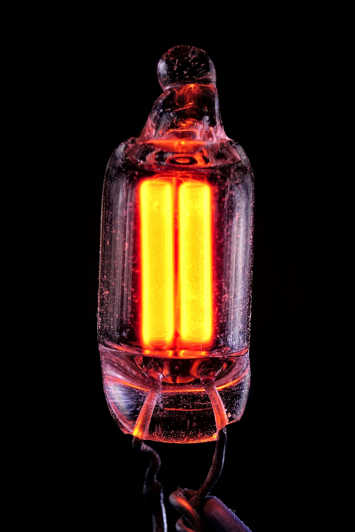
Why orange. Neon gas emits light at characteristic wavelengths determined by the electronic structure of neon atoms. The dominant emission lines of neon fall in the orange-red region of the visible spectrum, centred near 585–640 nanometres. This emission is not adjustable — it is a fixed physical property of neon gas. Every mechanical television image produced by a neon-lamp receiver is therefore orange. Not amber, not yellow, not a neutral grey: orange, the colour of neon. The tonal values (light and shadow, the graduation of a face from highlight to shade) are reproduced faithfully in terms of relative brightness, but all rendered in shades of orange. A Baird Televisor produces a monochrome orange image, not a greyscale one.
Why dim. The neon glow-lamp in a Televisor is a small device, producing limited total luminous output. It is viewed through a lens that focuses the image (typically with a magnifying positive lens to enlarge the postage-stamp-sized picture), and through the apertures of the spinning disc, each of which passes light for only a brief fraction of each frame. Since the disc has 30 apertures and each passes light for roughly 1/30 of the frame, and since the image must be reconstructed through the brief illumination of each strip, the average brightness reaching the eye is a fraction of the lamp’s already-modest output. Viewers invariably described the Televisor image as dim, and viewing was best done in a darkened room, with the eye close to the viewing hood, to allow dark adaptation and minimise competing ambient light.
Flat-plate construction. The neon lamps used in Baird Televisors were not the small cylindrical indicator lamps familiar from panel indicators. They were flat-plate neon lamps — sealed envelopes containing two flat parallel electrodes with a uniform gap between them, producing a flat glowing discharge area roughly the size of the image window. This flat-plate geometry gave a more uniform illumination of the aperture than a cylindrical lamp would, and a larger radiating area allowed more light to be collected through the disc apertures.
Viewing hood. Because the image is so dim, the standard Televisor design included a viewing hood — a light-tight enclosure around the display aperture into which the viewer inserted their face or eye, excluding ambient light and allowing the eye to dark-adapt to the lamp’s output. The experience of watching the Baird Televisor was accordingly intimate and somewhat laborious: leaning forward in a darkened room, face in a hood, watching a glowing orange stamp-sized image.
4.7 Synchronisation
Of all the engineering challenges in mechanical television, synchronisation was the most persistent and the most consequential for the viewer’s experience. The requirement is absolute: the disc at the receiver must rotate at exactly the same speed as the disc at the transmitter, and it must be in exactly the same phase — both in angular position and in frame position — so that each aperture at the receiver passes before the display lamp at precisely the moment the corresponding aperture at the transmitter is scanning the corresponding image area.
A speed error of even a fraction of a revolution per second causes the image to tear and drift. If the receiver disc rotates slightly faster than the transmitter disc, the image will appear to scroll in the frame direction — in the Baird system, left or right — as the phase drifts continuously forward. A viewer would see the image slowly rolling sideways, cycling around the frame every few seconds as the phase accumulated a full 360 degrees of error. Speed errors in the vertical sense (relative to the scanning direction, i.e., within one strip) manifest as vertical stretching or compression of the image. Phase errors that are fixed (not drifting) produce a stable but horizontally displaced image: the picture is there, but offset left or right from its correct position in the frame.
Speed lock. The primary synchronisation mechanism in the Baird broadcast system exploited the mains frequency relationship. The receiver’s scanning motor was a synchronous motor — a motor designed to rotate at a speed precisely governed by the frequency of its AC supply, rather than by load-dependent slip. A synchronous motor on the UK’s 50 Hz supply runs at a sub-multiple of mains frequency; with the correct winding, the disc turns at 12.5 rev/s (mains divided by four). Because every receiver and the BBC’s studio were on the same national grid, both shared the same 50 Hz frequency reference — providing the theoretical basis for speed lock. Whether a given motor held speed without manual intervention depended on its design and on mains stability; early domestic Televisors relied on the phasing and speed control described below, and the viewer was expected to trim it, rather than on guaranteed automatic lock.
Framing. Speed lock alone is not enough. Even two motors running at identical speed may be offset in phase — the transmitter aperture scanning Line 1 at the same moment the receiver aperture is showing Line 15, for example. This produces a fractured image, cut in two and rearranged, the head of the subject appearing at one edge and the feet at another. The phase relationship between the two discs is called framing, and the process of adjusting it is phasing.
In the Televisor, a phasing control — usually a small control knob on the receiver panel — allowed the viewer to adjust the angular position of the disc relative to its motor drive, shifting the phase in small increments until the image snapped into its correct position. This was not a set-and-forget adjustment: the phase could drift slowly over time, particularly as the motor and disc warmed up or as the mains frequency underwent minor variations, and periodic re-phasing was part of the routine of watching mechanical television.
Synchronisation pulses. From the earliest days of the BBC 30-line service, a synchronising signal was transmitted alongside the picture signal to help receivers lock to the correct frame phase. During the brief interval between the end of one frame and the beginning of the next, a brief electrical pulse was transmitted — a signal that the receiver could use to re-lock its framing. This frame synchronisation pulse is the direct ancestor of the synchronisation pulses used in all later television systems, electronic as well as mechanical. Without it, viewers would have needed to phase their receivers manually each time the broadcast began or was interrupted.
The difficulty of maintaining synchronisation — the need for a correctly designed motor, careful phasing, and periodic adjustment — meant that the domestic viewing experience was distinctly more demanding than switching on a radio. A detailed account of the phasing and sync circuitry of the Baird Televisor receiver appears in Vol 6 (Inside the Baird Televisor).
4.8 Signal Bandwidth and the Audio Channel
The signal bandwidth of a mechanical television system is not a free parameter: it is determined by the scanning parameters and constrained by the available channel. For the Baird 30-line system, the arithmetic runs as follows.
A signal of bandwidth B Hz can encode at most 2B distinct transitions per second (by the Nyquist sampling theorem). The line rate is 375 lines per second. In 1/375 of a second, a signal of bandwidth B can encode 2B/375 distinct picture elements. As a consistency demonstration — working backwards from the ~53 elements per line derived in the Mathematics section from the 10 kHz channel ceiling — the required bandwidth is (375 × 53) / 2 ≈ 9,940 Hz, which rounds to approximately 10 kHz, confirming the arithmetic is self-consistent.
For truly square picture elements given the 7:3 portrait format, the bandwidth rises to approximately 13 kHz, as documented by the NBTVA. In practice, the 10 kHz figure was the operative limit, set by the audio bandwidth available within a medium-wave broadcast channel.
The BBC’s medium-wave transmitters of the 1929–1935 period had audio passbands extending to approximately 9–10 kHz. The Baird 30-line video signal — spanning from DC (representing average brightness) up to approximately 10 kHz (representing the finest brightness variations) — fit within this audio passband. This is why the BBC could transmit television pictures on its existing medium-wave radio transmitters after the main radio programme of the evening had ended: the television signal occupied exactly the same frequency band as an audio programme and required no modification to the transmitter hardware.
The same property — the entire video signal fitting within an audio bandwidth — explains why Phonovision was possible. John Logie Baird’s experimental system for recording television onto gramophone discs, described fully in Vol 8 (The 30-Line Broadcast Era), exploited the fact that the video signal’s frequency range was identical to that of an audio signal. A standard disc-cutting lathe, designed to record sound in the range of 100 Hz to 10 kHz, could cut a Baird television signal onto wax directly. The recording and playback apparatus required no modification; only the interpretation of the signal was different.
The audio-bandwidth property of the 30-line signal was not an accidental benefit. It was a fundamental consequence of the low resolution and low frame rate chosen for the system, and it is perpetuated deliberately in the modern NBTV 32-line standard. Modern NBTV signals, as described in Vol 12 (The NBTV Signal Explained), are designed explicitly to lie within the audio passband, allowing them to be transmitted over audio equipment, recorded on audio media, and distributed through audio channels — a design philosophy that traces directly back to the engineering constraints of 1929.
4.9 An Honest Account: Small, Dim, Orange, Low-Resolution, Portrait
No account of the Baird 30-line system is complete without a candid summary of the viewing experience. The system’s partisans, the BBC’s press releases, and the enthusiastic accounts of early viewers inevitably emphasise the miraculous novelty of seeing a live image transmitted through the air. What they describe, measured against any modern standard of image quality, was this:
Small. The Baird Televisor produced an image approximately 30 mm × 70 mm in the standard display configuration — postage-stamp to playing-card sized. Some implementations used a magnifying lens to enlarge the image, but this also amplified the optical distortions and was constrained by the limited brightness of the neon lamp. The image area was fundamentally limited by the geometry of the Nipkow disc and the neon lamp: a larger image required a larger aperture (admitting more light but reducing resolution) or a brighter lamp (beyond the available technology).
Dim. The neon glow-lamp produced perhaps a few milliwatts of useful optical output through the disc apertures. Viewing required a darkened room and close proximity to the display. Bright ambient light overwhelmed the image entirely.
Orange. As described above, the neon gas emission spectrum admits no other colour. Every tonal value — every gradation from facial highlight to deep shadow — was rendered in shades of orange. This was understood at the time and considered an acceptable limitation; the reproduction of recognisable moving images at all was remarkable enough that the colour of those images was a secondary concern.
Low-resolution. Approximately 1,600 picture elements per frame, arranged in 30 columns and roughly 53 rows, with no interlacing or other resolution-enhancement technique. Close-up head shots — filling the frame with a single face — were the only practical subject; any more complex scene dissolved into orange smears. The system was, in its own terms, a “head-and-shoulders” medium.
Portrait. The 3:7 width-to-height format (7 units tall, 3 units wide) suited the head-and-shoulders close-up and nothing else. Landscape scenes, group shots, and objects wider than they were tall were poorly served by this format. It was the correct format for the available resolution; it was also the only subject at which the system was even marginally adequate.
These are not criticisms of the engineering — they are inherent consequences of the available technology and the choices made to keep the signal within an audio channel. The Baird 30-line system achieved what it achieved: a recognisable, live, moving human image transmitted through the air to a domestic receiver. That it did so in orange, at postage-stamp size, with a flicker visible in peripheral vision, is the honest description of what the viewer saw.
The full technical internals of the Baird Televisor receiver — motor, disc, synchronisation circuitry, neon lamp, framing control — are examined in Vol 6 (Inside the Baird Televisor). The question of how far the mechanical approach could be pushed beyond these limits is taken up in Vol 9 (Pushing the Limits).
Comments (0)